PathMaster-REV-L-4.5-1.pdf - 第49页
Machine Operati on Manual Revision L / February 2020 Page 49 of 2 00 5. Sele ct the Z Position from the drop - do wn me nu . The Z component of th e workspac e referen ce can be chosen from the curren t positio n, a posi…
Machine Operation Manual
Revision L /
February 2020
Page 48 of 200
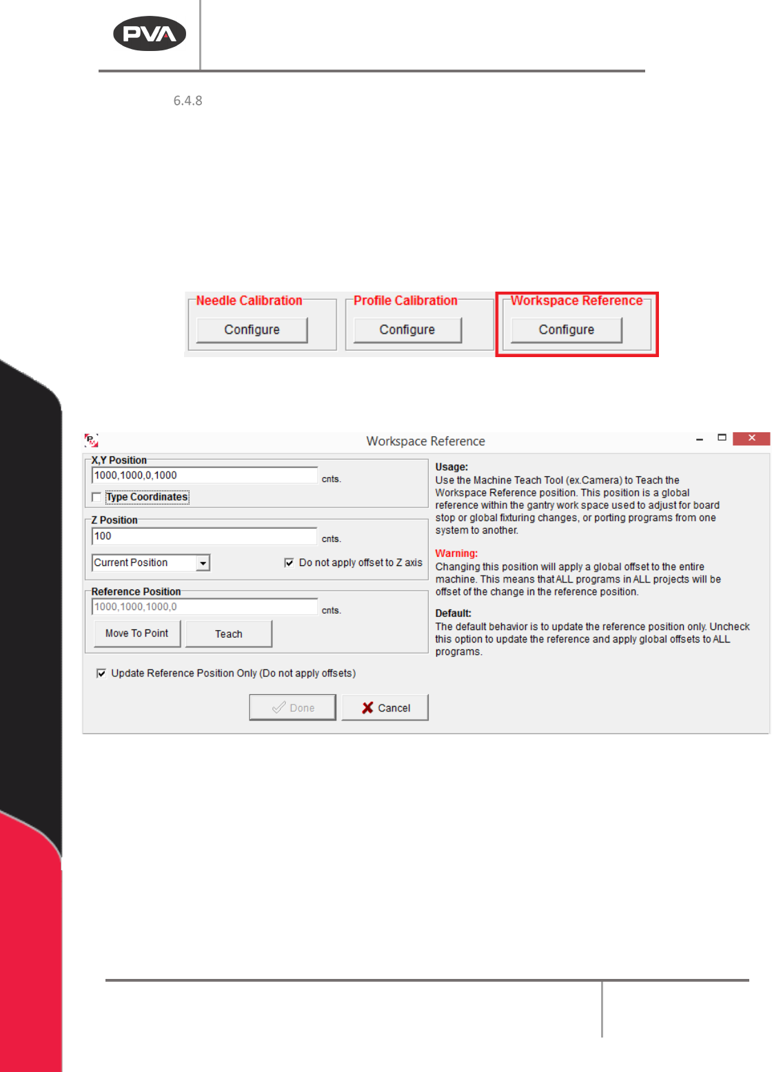
Workspace Reference
Workspace reference is a global reference position used to help make a machine program
transport or a global offset to the local system.
To teach a workspace reference point, on a typical system, put the machine calibration
plate against the board stops and put the teach tool at the cross hair on the machine
calibration plate. The workspace reference point must reference the part workspace so
that if the part fixture changes, due to board stop location, etc., the workspace reference
point moves with it.
Figure 41: Workspace Reference
1. Select the Workspace Reference “Configure” button.
Figure 42: Workspace Reference Window
2. Click the “Move To Point” button to move to the workspace reference position.
3. If the Move to Point button is not in the correct location, use the teach tool to move
to the necessary workspace reference position. Click the
“Teach” button to teach
the workspace reference position.
4. The Update Reference Position Only checkbox is checked by default. This will
update the workspace reference position but not apply program offsets (The
difference between the original workspace reference and the new workspace
reference). Uncheck this box to apply global offsets to all programs.
Machine Operation Manual
Revision L /
February 2020
Page 49 of 200
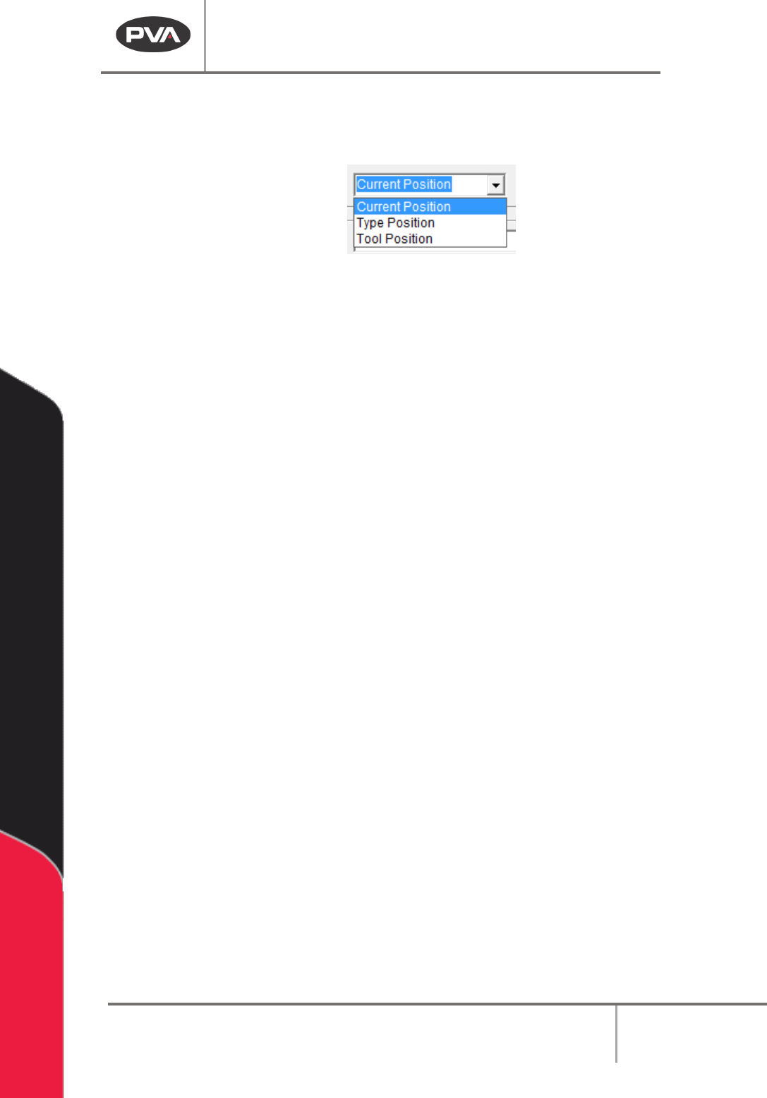
5. Select the Z Position from the drop-down menu. The Z component of the
workspace reference can be chosen from the current position, a position that is
typed in, or from the tool position of the tool Z offset.
Figure 43: Select the Z Position
6. Select the Do not apply offset to Z axis checkbox, if the Z offset should not be
included.
7. When the settings have been set, select the “Done” button, or select “Cancel” to
exit and not save changes.
NOTE: The Teach Tool option must be enabled and the machine must be in Manual mode to
teach the workspace reference position.
Machine Operation Manual
Revision L /
February 2020
Page 50 of 200
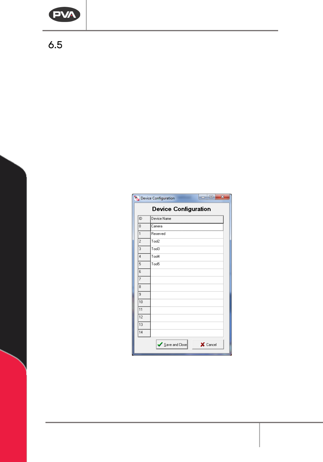
Devices
PathMaster® can have up to 15 devices configured if the teach tool is enabled. All Devices
are physical tools in the system. Devices are used to relate a Virtual Tool to a physical tool.
These settings are found in the Machine Parameters window.
1. Select
Setup->Machine Parameters
from the Main menu to open the Machine
Parameters window.
2. To configure the devices in the system, click ‘Devices’ in the Virtual Tools section of
Machine Parameters.
3. From here you can name all the Devices in the system. Any name that is left blank
will be unavailable to use to teach paths and during playback.
With the Teach Tool function in PathMaster, the first device will be the teach tool (device 0)
by default. If a workcell does not have a teach tool, the first tool spot will be reserved. If a
teach tool is added on the workcell later, the reserved first tool will become the teach tool
and prevent many programming changes.
Figure 44: Tool Name and Configuration
NOTE: Devices must be listed in sequential order. For example, if Device 5 is left blank, all
following Devices will be unavailable for playback and teaching. If a tool is deleted it will not
be available.