PathMaster-REV-L-4.5-1.pdf - 第60页
Machine Operati on Manual Revision L / February 2020 Page 60 of 20 0 Figure 56 : Tool Sele ction Wind ow 3. Selec t the “ OK ” but ton. Figure 57 : Too l Offset Window 4. Align the selec ted tool with the refe rence po s…
Machine Operation Manual
Revision L /
February 2020
Page 59 of 200
2. Teach the Dispense Position with the teach button, this is the location the dot will
be dispensed. The dispense position is stored for this tool.
3. Set the On Time in seconds. This is how long the tool will operate to dispense the
dot.
4. Select “Run” to dispense the dot for the set On Time.
5. Move the teach tool to the dispensed dot and teach the position.
6. When the tool offsets have been taught for each tool, select the “Done” button, or
select
“Cancel” to exit and not save changes.
NOTE: If Dot Drop Mode is enabled for a tool, that tool will reference Dot Drop mode when a
Tool Change is done.
NOTE: If a Dispense Position is taught, the Run Tool reference position will be calculated
automatically and can be used when you exit Dot Drop mode.
Tool Change
A Tool Change adjusts the tool offset and applies a program offset to correct the position
of a tool. A tool change should be done after a needle is changed, or if a tool installed after
maintenance has been done. A tool change should be done after any change in the
physical location of a tool tip.
NOTE: The teach tool option must be enabled to use the tool change function.
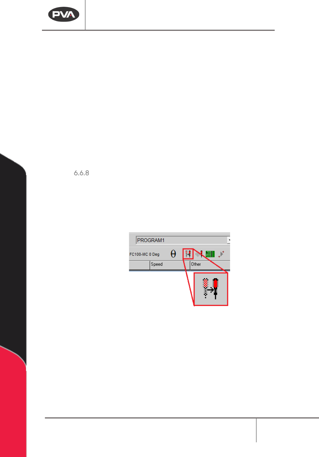
Figure 55: Tool Change Button
1. Select the Tool Change button on the main tool bar.
2. Select a tool from the Tool Selection window.
Machine Operation Manual
Revision L /
February 2020
Page 60 of 200
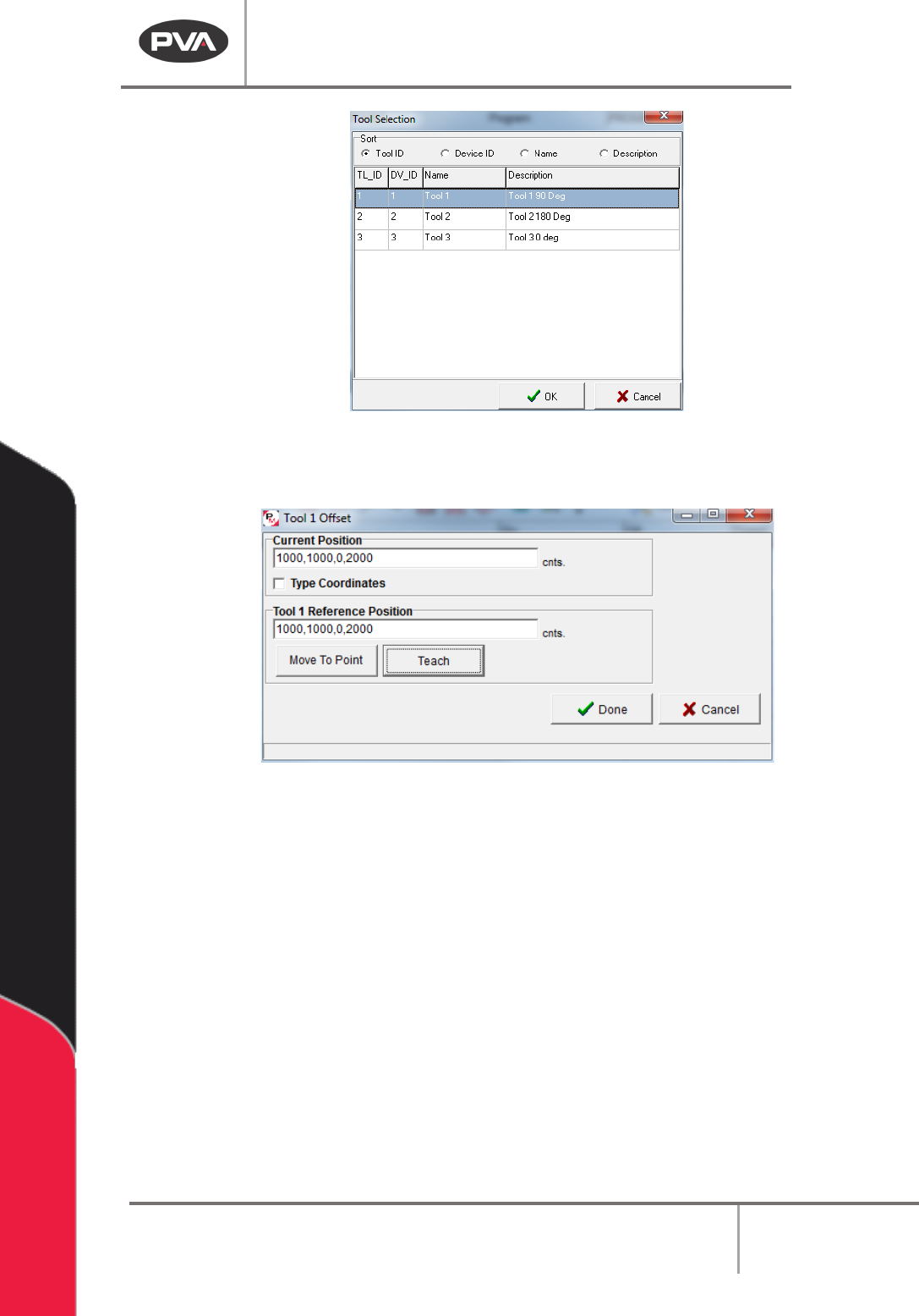
Figure 56: Tool Selection Window
3. Select the “OK” button.
Figure 57: Tool Offset Window
4. Align the selected tool with the reference position (the same position referenced by
the Teach Tool). You can use the “
Move To Point” button to move to the run tool
reference position.
5. Select the “Teach” button to teach the run tool reference position.
6. Select the “Done” button, or select “Cancel” to exit and not save changes.
7. If “Use Profile Calibration” is enabled on the current tool, the Tool Calibration for
changing the
Profile Offset will automatically run.
Machine Operation Manual
Revision L /
February 2020
Page 61 of 200
Tool Calibration
A tool calibration must be done after a needle is changed, if a tool is installed, or after any
change in the physical location of a tool. The purpose of a tool calibration is twofold:
• If “Use Needle Calibration” is enabled on a virtual tool’s Tool Configuration, the Tool
Calibration Function adjusts the tool offset and applies a program offset to correct
the position of the tool’s tip.
• If “Use Profile Calibration” is enabled on a virtual tool’s Tool Configuration, the Tool
Calibration Function adjusts the
Profile Offset for the tool.
NOTE: Enable the teach tool option to use the Tool Calibration function.
Figure 58: Tool Calibration
WARNING: The tool offsets, the Needle Calibration Sensor Locate Sequence (if applicable)
AND the Profile Plunger Locate Sequence (if applicable) must be set up before a Tool
Calibration is done, or the system could be damaged.
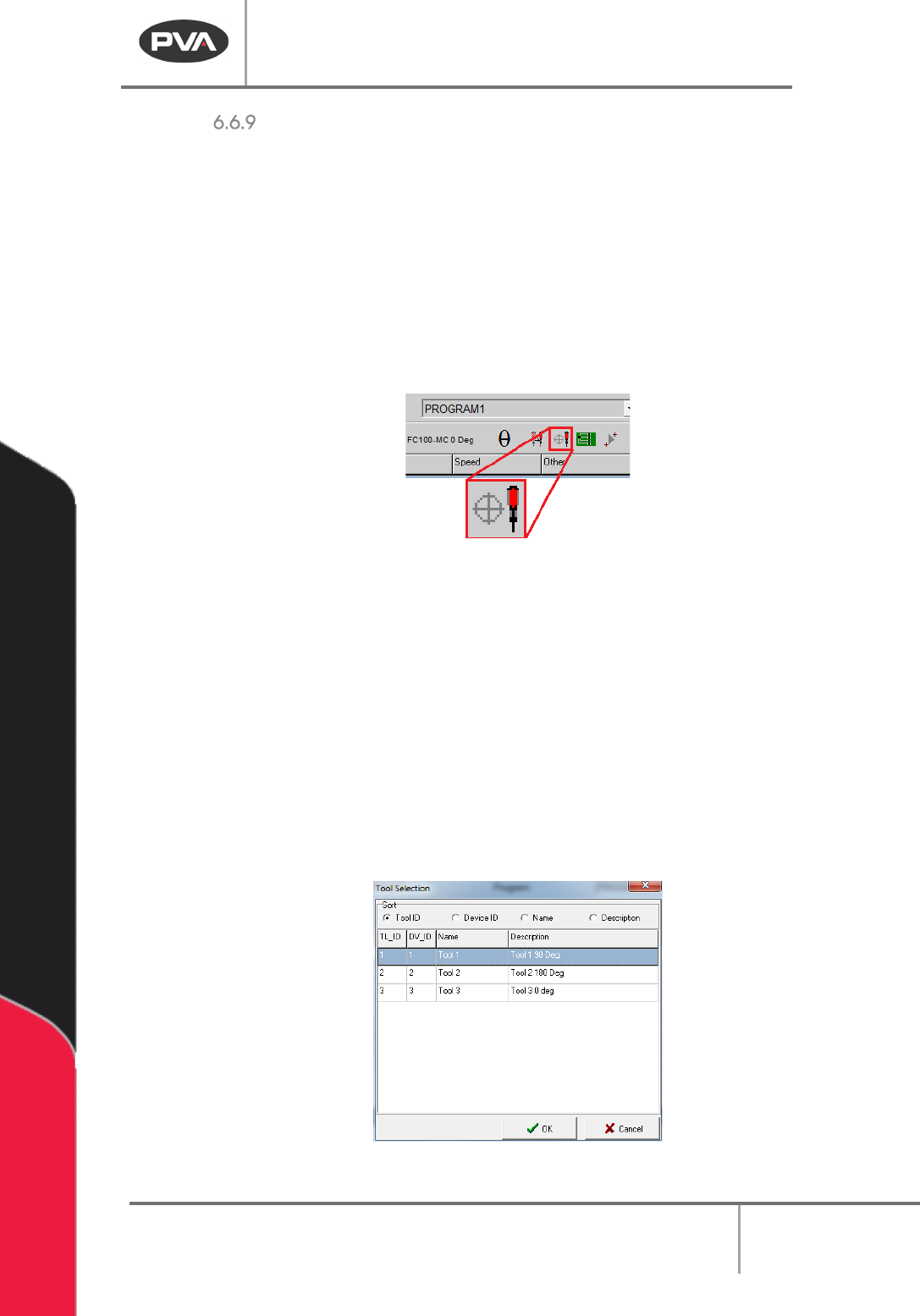
1. Select the Tool Calibration button on the main tool bar.
2. Select the necessary tool from the Tool Selection window. Multiple, consecutive
tools can be selected. Use the
Sort buttons to sort the tools so the necessary tools
are listed consecutively. Hold the “
Shift” key and click or click and drag to highlight
the tools to calibrate.
NOTE: For a tool to show up in the tool selection list, the “Use Needle Calibration” checkbox
or the “Use Profile Calibration” must be checked in the Tool Configuration window.
Figure 59: Tool Selection Window