2OM-1075-002.pdf - 第142页
AHB01ESPP (a) When "Disable" is specified for the alternated feeder mode, the "Altn Fdr Mode" tab sheet looks as follows. Fig. 2E1 1 "Altn Fdr Mode" T ab Sheet (Alternate Feeder Mode: Disabl…

AHB01ESPP
*3 "F1", "F3", and "F4"
The feeder Nos. and the destination feeder Nos. are colored, indi-
cating whether the alternate feeder mode is enabled or disabled.
"Disable" is automatically set for the feeder No. where a component
shortage error is detected.
"Enable" is automatically set when the feeder is installed after com-
ponent replenishment.
When the alternate feeder mode must be manually changed
from "Enable" to "Disable" or vice versa, select the objective
feeder No. and press the [Enable] or the [Disable] button in "*4".
*4 Specified Contents
The feeder No. selected in "*3" appears in the "Fdr No." text box.
When the [Enable] or [Disable] button is pressed, "Enable" or "Dis-
able" is changed or vice versa for the selected feeder, indicating
that the status of the alternate feeder mode is changed.
*5 Comp ID, Type, Dir
Displayed are the component ID, the type, and the direction of the
feeder No. selected in "*3".
*6 [Enable All F1] Button
The alternate feeder mode is enabled for all feeders on the feeder
base selected in "*3" (Feeder Base #1 in this case).
*7 [Jump to Alt Fdr] Button
The feeder Nos. selected in "*3" are specified as the destination
ones for the alternate feeder mode.
3.2 "Altn Fdr Mode" Tab
0206-001 5-14-2
Note

AHB01ESPP
(a) When "Disable" is specified for the alternated feeder mode,
the "Altn Fdr Mode" tab sheet looks as follows.
Fig. 2E11 "Altn Fdr Mode" Tab Sheet (Alternate Feeder Mode: Disable)
(b) The parameters specified here become valid prior to the
other alternate-related ones that are designated in the pat-
tern program.
Even when "Enable" is set in the pattern program, this al-
ternate feeder mode (function) can be used to temporarily
set "Disable" in relation to preparation for the feeders.
(c) The set parameters ("Enable" or "Disable" (alternate feeder
modes) for each individual feeders) are saved when the
[POWER ON] or the [POWER OFF] button is pressed,
the system is cleared, or the current pattern program data
is modified.
3.2 "Altn Fdr Mode" Tab
0206-001 5-14-3
Note
AHB01ESPP
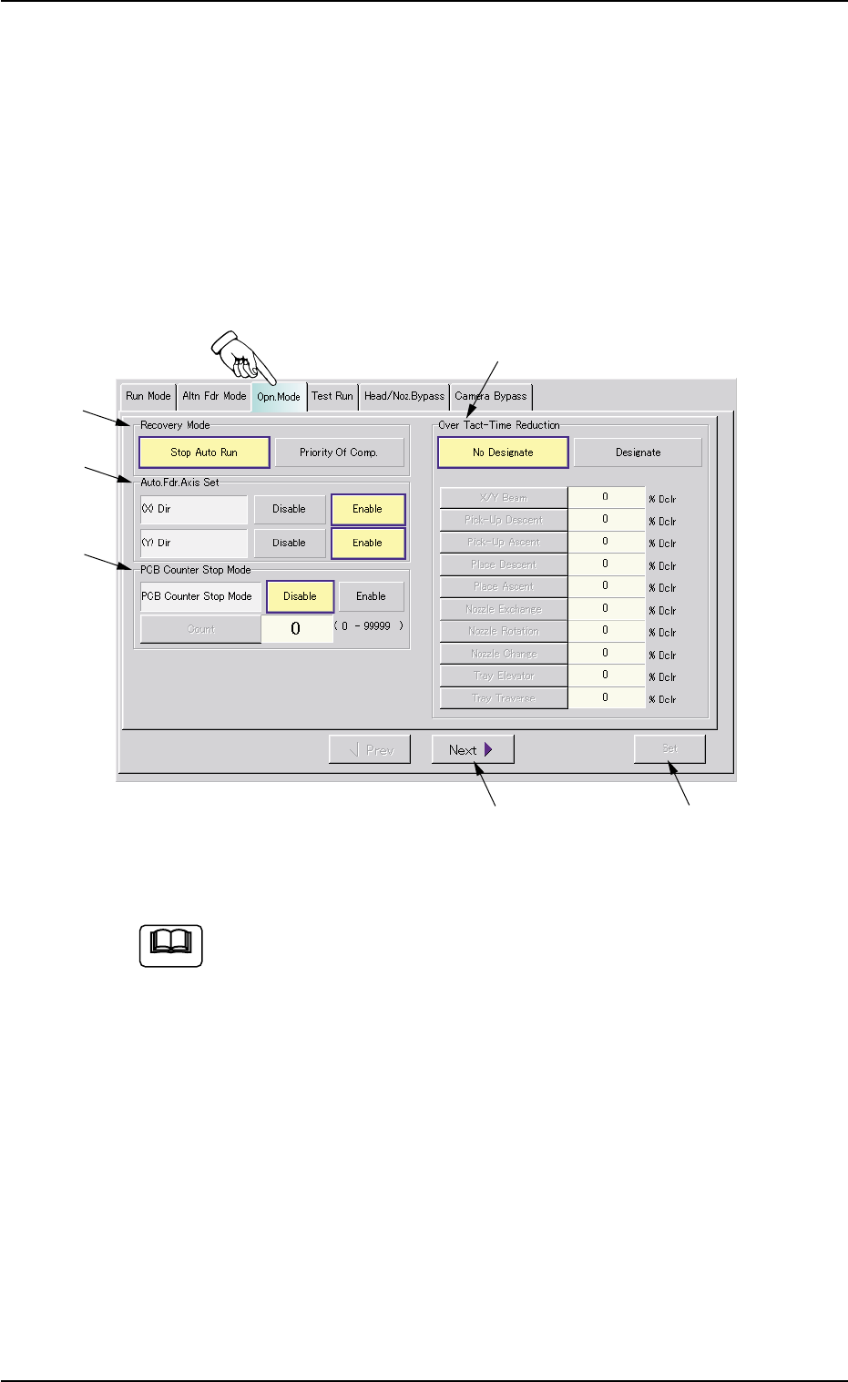
3.3 "Opn. Mode" Tab
The corresponding tab sheet enables the operator to specify various
operation modes such as "Recovery Mode", "Auto. Fdr. Axis Set", "PCB
Counter Stop Mode", etc.
• Sheet Layout
When the "Opn. Mode" tab is pressed in the "OPN. MODE" window
(submenu), the following tab sheet appears inside the window.
Fig. 2E12 "Opn. Mode" Tab Sheet (Provided with Multi-Layer Tray Feeder 2)
The tab sheet may look different, depending on which options
are selected.
• Sheet Composition
*1 Recovery Mode
It can be determined in which mode "Stop Auto Run" or "Priority Of
Comp." the machine should be set when a component shortage
error is detected.
[Stop Auto Run] Button
When a component shortage error is detected, the machine stops
running immediately.
3.3 "Opn. Mode" Tab
0206-003 5-15
*5
*3
*2
*1
*4
*6
Note