2OM-1075-002.pdf - 第374页
AHB01ESPP (1) Graphical Representation The following shows the relation between the component library data and the graphical representation and the coloring for each individual component shapes. The graphics related to t…
AHB01ESPP
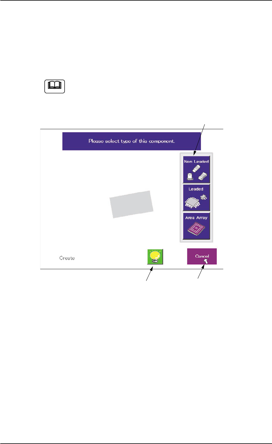
5.2.10 Navigations in "Recognition" Window
The "Recognition" window is composed of various subwindows that have
component icons, etc. inside.
Move the cursor to the button (an item or a function) to be selected and
click it. The item or the function is selected.
Use the pointing device.
When the touch screen is pushed by finger, it shows no reac-
tion.
Fig. 2F104-17 Example of Window Layout
The framed subwindow can be moved to another place within the win-
dow.
When a subwindow has a title, click the title and drag it to another place.
When a subwindow has no title, click the upper area of the subwindow
and drag it to another place.
This function can be used when part of an image is hidden behind a
subwindow.
5.2 Library Teaching
0308-004 6-141
Framed Subwindow
Frameless Subwindow
Cursor
Note
AHB01ESPP
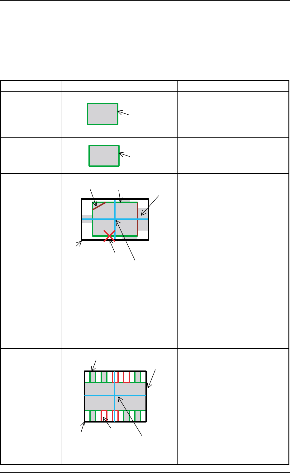
(1) Graphical Representation
The following shows the relation between the component library data
and the graphical representation and the coloring for each individual
component shapes.
The graphics related to the parameters to be edited are expressed
in yellow in the data edit window.
Table 2F16
Component Shape Example of Graphic Representation Displayed Parameters
Cylindrical A: Mold size X [mm], Y [mm]
Square A: Mold size X [mm], Y [mm]
Deformed A: Mold size X [mm], Y [mm]
B: Outward length 1 [mm] through
4 [mm]
C: Component Center
Center of Outward Length
D: Each Corner’s Dimensions X, Y
Note: When "No Detection" is set in
the "Shape" text box in the
"Corner Data" tab sheet, the
corner is expressed in gray.
When "Straight" is set, the cor-
ner is not displayed.
E: Each Edge Detection Posn X [mm],
Y [mm]
This appears only when
"Convexoconcave" is set in the
"Shape" text boxes in the "Edge Data"
tab sheet.
F: Each Edge
This appears in dark red only when
"No Detection" is set in the "Shape"
text boxes in the "Edge Data" tab
sheet.
Leaded
IC
Connector
Other Leaded
5.2 Library Teaching
0308-004 6-142
A: Mold size X [mm], Y [mm]
B: Outward length 1 [mm] through
4 [mm]
C: Component Center
Center of Outward Length
D: Each Lead Data
Width = Lead Width
Height = Lead Length and
Full Lead Length
Position = Calculated based on the
lead group data
E: Missing Lead Data
Calculated based on the lead group
data
A (Green)
A (Green)
A (Green)
C (Light Blue)
E (Red)
B (White)
D (Violet)
F (Dark Red)
D (Green)
A (Green)
B (White)
E (Red)
C (Light Blue)
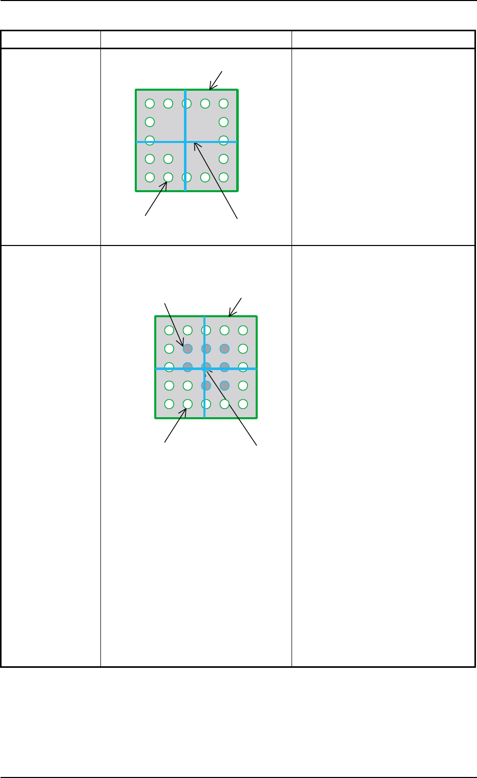
AHB01ESPP
Table 2F17
Component Shape Example of Graphic Representation Displayed Parameters
BGA (Normal) A: Mold size X [mm], Y [mm]
B: Component Center
Center of Mold Size X, Y
C: Each Ball Data
Diameter : Ball Diameter
Position : Each Ball Group
Calculated based on
each ball group data
During Data Editing A: Mold size X [mm], Y [mm]
B: Component Center
Center of Mold Size X, Y
C: Each Ball Data
Diameter: Ball Diameter
Position : Calculated based on
each ball group data
Yellow : Balls in Object Group for
Editing
Green : Balls in Other Block
(block other than object
one for editing)
D: Each Missing Ball Data
Diameter: Ball Diameter
Position : Calculated based on
each ball group data
Light Blue :
Balls in Object Missing
Block for Editing
Red : Balls in Other Missing
Block (missing block
other than object one for
editing)
Note: All missing balls are expressed
in red in any edit windows other
than the edit window for the
missing ball data.
5.2 Library Teaching
0308-004 6-143
A (Green)
C (Green)
B (Light Blue)
D (Red, Light Blue)
A (Green)
C (Green)
B (Light Blue)