2OM-1075-002.pdf - 第242页
AHB01ESPP 3 . 1 "X/Y Beam T est" T ab The corresponding tab sheet enables the operator to check the X/Y beam movement according to the current pattern program. The P .E.C. recognition camera captures an image o…
AHB01ESPP
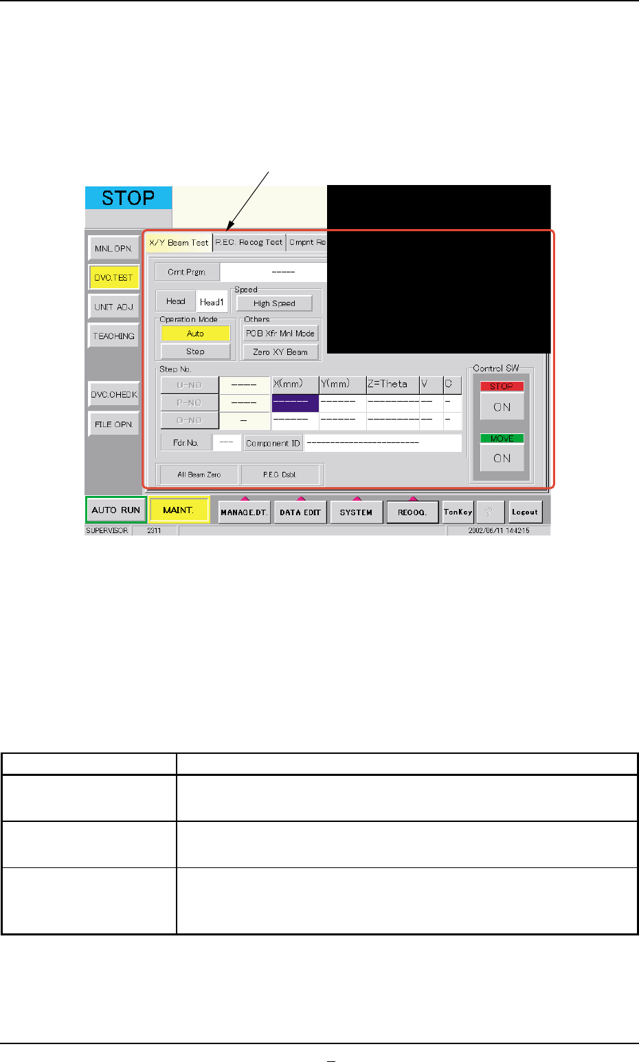
3. "DVC. TEST" Window (Submenu)
• Window Layout
When the [DVC. TEST] button on the submenu bar is pressed in the
"MAINT." window, the following window (submenu) opens.
Fig. 2F7 "DVC. TEST" Window (Submenu)
• Window Composition
*1 Tabs
The "DVC. TEST" window (submenu) is provided with the following
3 tabs. When a tab is pressed, the corresponding tab sheet ap-
pears inside the window.
Table 2F4
Tabs Description
X/Y Beam Test The corresponding tab sheet enables the operator to check the X/
Y beam movement according to the current pattern program.
P.E.C. Recog Test The corresponding tab sheet enables the operator to make a test on
the P.E.C. recognition (fiducial) marks.
Cmpnt Recog Test The corresponding tab sheet enables the operator to perform a com-
ponent recognition test on the component specified in the "TEST ID"
text box.
0206-003 6-12
3. "DVC. TEST" Window (Submenu)
*1
AHB01ESPP
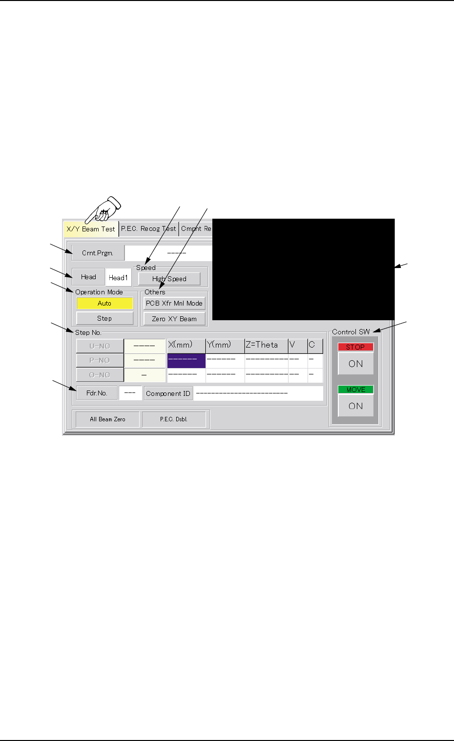
3.1 "X/Y Beam Test" Tab
The corresponding tab sheet enables the operator to check the X/Y beam
movement according to the current pattern program.
The P.E.C. recognition camera captures an image of the placement
position in the order of the pattern programs.
••
••
• Sheet Layout
When the "X/Y Beam Test" tab is pressed in the "DVC. TEST" window
(submenu), the following tab sheet appears.
Fig. 2F7-1 "X/Y Beam Test" Tab Sheet
••
••
• Sheet Composition
*1 Crnt. Prgm.
Displayed is the currently selected pattern program name.
*2 Recognized Image
The image of the recognized P.C.B. is displayed.
When this area is pressed, the recognized image disappears.
*3 Head
Displayed is the head No. specified in the pattern program.
3.1 "X/Y Beam Test" Tab
*1
*9
*3
*5
*7
*8
*2
*4
*6
0206-001 6-12-1

AHB01ESPP
*4 "Speed" Group Box
Set the time during which the X/Y beam should stay still at the place-
ment point.
When the button in the group box is pressed, the label changes in
scrolling such as "High Speed" Æ "Mid. Speed" Æ "Low Speed".
High Speed : 50 msec
Mid. Speed : 1000 msec
Low Speed : 2000 msec
*5 "Operation Mode" Group Box
[Auto] Button
When this button is selected and the [ENABLE] button on the
operation panel is pressed in 2 seconds after the [ON] button
(entitled "MOVE"), the X/Y beam moves in succession according
to the pattern program.
[Step] Button
When this button is selected and the [ENABLE] button on the
operation panel is pressed in 2 seconds after the [ON] button
(entitled "MOVE"), the X/Y beam moves step by step according to
the pattern program.
*6 "Others" Group Box
[PCB Xfr Mnl Mode] Button
When pressed, this button opens the "PCB Xfr Mnl Mode" sheet.
(Not available at present)
[Zero XY Beam] Button
When this button is selected and the [ENABLE] button on the
operation panel is pressed in 2 seconds after the [ON] button
(entitled "MOVE"), the X/Y beam starts returning to its origin (ze-
roing).
*7 "Step No." Group Box (Step Designation)
Press one of the following buttons. The edit window opens. Desig-
nate the step No. in the pattern program with which an X/Y beam
test must be started.
[U-NO] Button : When this button is pressed, the corresponding
edit window opens. Designate the step No. (U-
No.).
[P-NO] Button : When this button is pressed, the corresponding
edit window opens. Designate the step No. (P-
No.).
[O-NO] Button : When this button is pressed, the corresponding
edit window opens. Designate the step No. (O-
No.).
3.1 "X/Y Beam Test" Tab
0206-001 6-12-2