2OM-1075-002.pdf - 第56页
• Principle of Recognition (1) Back Lighting Recognition System The figure shows the sectional view of the recognition unit and the flow of recognition light in the back lighting recognition sys- tem. • As for the compon…
1.2.3 Preparation for Component Placement
Movable and Fixed Cameras:
Image Capture for Component Recognition and Component
Recognition
• The movable or the fixed camera captures an image of the compo-
nent for recognition.
The component recognition camera is automatically selected ac-
cording to the component library data.
• The machine is provided with two component recognition systems
- "Back Lighting Recognition System" and "Front Lighting Recogni-
tion System". The lighting method specified in the component li-
brary is automatically selected.
The following component recognition takes place.
(1) Component Detection
All components can be detected.
(2) Component Inspection
Each inspection is made according to the component library.
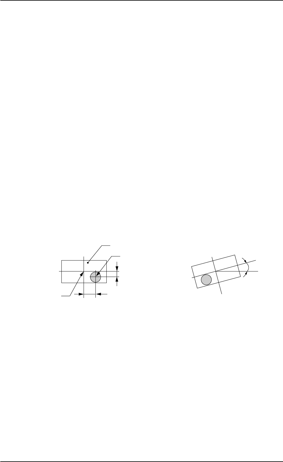
(3) Measurement of Positional Deviation (X, Y) and Angular
Deviation (θ) between Component Recognition Camera
Center and Component Center
Fig. 2B9 State of Component Picked Up by Vacuum Nozzle
0206-003 2 -6
AHB01ESPP
1.2 Component Placement (starting with preparation for component picks)
Component
Vacuum Nozzle
Component Center
Y
X
θ
Positional Deviation X and Y
Angular Deviation θ
(deviation from correct direction)
• Principle of Recognition
(1) Back Lighting Recognition System
The figure shows the sectional view of the recognition unit and
the flow of recognition light in the back lighting recognition sys-
tem.
• As for the component shown by the diagonal lines, the outline
is recognized through fixed back lighting.
Fig. 2B10
The light emitted from the back lighting lamp meets the diffusion plate
(assembled together with the nozzle) and reflects to the component. At
this time, the light which does not meet the component enters into the
CCD camera through the monocular. That is, the CCD camera cap-
tures the image of the outline of the component.
Fig. 2B11 Image on Recognition Monitor (Example)
0206-003 2 -7 AHB01ESPP
1.2 Component Placement (starting with preparation for component picks)
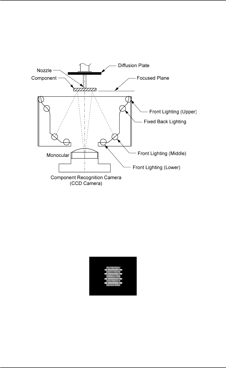
(2) Front Lighting Recognition System
The figure shows the sectional view of the recognition unit and
the flow of the recognition light in the front lighting recognition sys-
tem.
Select the proper lighting system, using the front lighting lamps
(upper, middle, and lower) for component recognition.
Fig. 2B12
The light emitted from the front lighting lamps (upper, middle, and lower)
meets the bottom of the component. The reflected light enters into the
CCD camera through the monocular.
That is, the CCD camera captures the image of the component leads,
etc.
Fig. 2B13 Image on Recognition Monitor (Example)
0206-003 2 -8 AHB01ESPP
1.2 Component Placement (starting with preparation for component picks)