2OM-1075-002.pdf - 第397页
AHB01ESPP 5 . 8 "Cmpnt Recog Fxd Camr Ofs" T ab The corresponding tab sheet enables the operator to perform a teach- ing operation on the offsets of the component recognition camera (fixed). When the recognitio…

AHB01ESPP
(a) When each device is not zeroed and the teaching op-
erations are performed, note that the offset values may
not be taught correctly.
(b) Before performing a teaching operation, be sure to zero
all beams.
*5 Offset Values
Displayed are the current values and the adjusted ones after teach-
ing.
*6 [Vacuum Pick-Up On/Off] Button
When this button is pressed, the vacuum of the selected head is
turned ON or OFF.
*7 Vacuum Pick-Up Mode
Displayed is the vacuum ON/OFF mode of the selected head.
Blue Background : Vacuum OFF
No Background Color : Vacuum ON
*8 [Manual Nozzle Change] Button
When this button is pressed, the "Nozzle Change" sheet appears.
Refer to "4.4 "Nozzle Change" Tab" for details.
*9 [Clear Adj.] Button
When pressed, this button clears the results of the teaching opera-
tion.
*10 [Cancel] Button
When pressed, this button ends the teaching operation without re-
flecting the teaching results on the offset data.
*11 [End] Button
When pressed, this button reflects the results of the teaching op-
eration on the offset data and exits from this session.
*12 "Control Switch" Group Box
Select the items (buttons) to be taught and press the [ON] button
entitled "MOVE". After that, press the [ENABLE] button on the op-
eration panel in 2 seconds. A teaching operation is performed on
the selected item.
Note
0206-002 6-162
5.7 "Cmpnt Fxd Camr Mag" Tab
AHB01ESPP
5.8 "Cmpnt Recog Fxd Camr Ofs" Tab
The corresponding tab sheet enables the operator to perform a teach-
ing operation on the offsets of the component recognition camera (fixed).
When the recognition is performed at the same time, using the P.E.C.
recognition camera and the fixed camera after a jig component is set on
the fixed camera, the deviation from the design position to the fixed cam-
era can be determined.
This teaching operation must be performed only by our service
personnel.
• Sheet Layout
When the "Cmpnt Recog Fxd Camr Ofs" tab is pressed in the "TEACH-
ING" window (submenu), the following tab sheet appears inside the win-
dow.
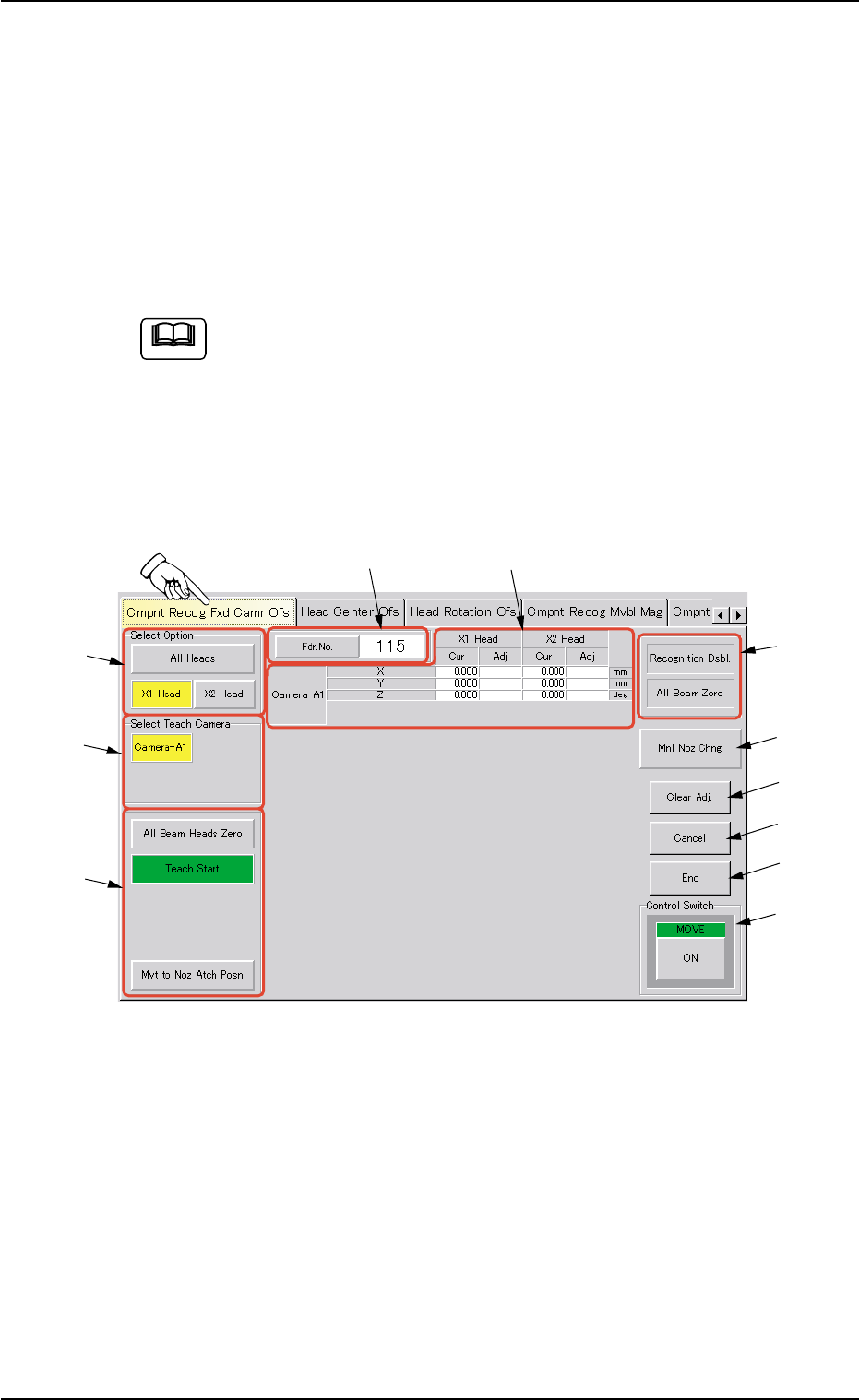
Fig. 2F113 "Cmpnt Recog Fxd Camr Ofs" Tab Sheet
0206-002 6-163
5.8 "Cmpnt Recog Fxd Camr Ofs" Tab
Note
*7
*8
*10
*11
*1
*2
*3
*5
*6
*4
*9

AHB01ESPP
• Sheet Composition
*1 "Select Option" Group Box
The following buttons are provided.
[All Heads] Button
When this button is pressed, a teaching operation on the off-
sets of the component recognition camera (fixed) is performed,
using both heads.
Before performing the teaching operation, zero all beams.
[X1 Head] and [X2 Head] Buttons
A teaching operation on the offsets of the component recogni-
tion camera (fixed) can be performed, using either one of the
X1 and X2 heads.
Before performing the teaching operation, zero all beams.
*2 "Select Teach Camera" Group Box
Select the fixed camera to be used for the teaching operation.
The following button is provided in this group box.
[Camera-A1] Button
*3 "Selection of Teaching Operation" Group Box
The following buttons are provided in this group box.
[All Beam Heads Zero] Button
When this button is pressed, all X/Y beams are zeroed.
[Teach Start] Button
When this button is pressed, the machine performs a teaching
operation on the selected item.
[Movement to Nozzle Attachment Position] Button
When this button is pressed, the head moves to the specified
feeder No. (Fdr. No.) position.
*4 Set Status
When the "P.E.C. Dsbl." or the "Comp. Recognition Dsbl." check
box in the "Test Run" window is turned on (checked), the background
color of "Recognition Dsbl." turns light red. (No background color in
normal cases).
Note
0206-002 6-164
5.8 "Cmpnt Recog Fxd Camr Ofs" Tab
Note