2OM-1075-002.pdf - 第371页
AHB01ESPP • When the shape of the leaded component is "IC (Simple)", "IC (Complex)", "Connector (Simple)", "Connector (Complex)", or "Other Leaded (Simple)", verify the f…
AHB01ESPP
5.2.8 Helpful Hints for Parameter Verification
After a teaching operation is completed, press the [Table Disp] button to
verify the parameters.
Special attention should be paid to the following items because the
amount of correction for component recognition is affected by them.
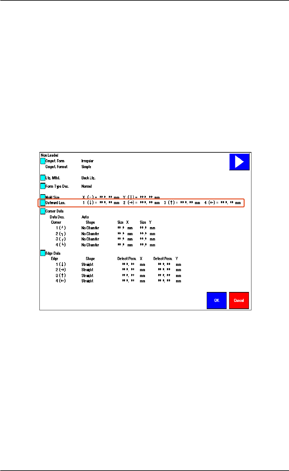
• When the shape of the leadless component is "Deform (Simple)",
verify the following.
Verify that the same values are obtained for "1 (È)" and "3 (Ç)" en-
titled "Outward Len." for the vertically symmetrical component.
Verify that the same values are obtained for "2 (Æ)" and "4 (Å)" en-
titled "Outward Len." for the horizontally symmetrical component.
Fig. 2F104-12
5.2 Library Teaching
0308-004 6-138
AHB01ESPP
• When the shape of the leaded component is "IC (Simple)", "IC
(Complex)", "Connector (Simple)", "Connector (Complex)", or
"Other Leaded (Simple)", verify the following.
Verify that the same values are obtained for "1 (È)" and "3 (Ç)" en-
titled "Outward Len." for the vertically symmetrical component.
Verify that the same values are obtained for "2 (Æ)" and "4 (Å)" en-
titled "Outward Len." for the horizontally symmetrical component.
When the center of the lead group is located at the center of the com-
ponent, verify that "0 (zero)" is obtained for "Posn. (Latl.)".
Fig. 2F104-13
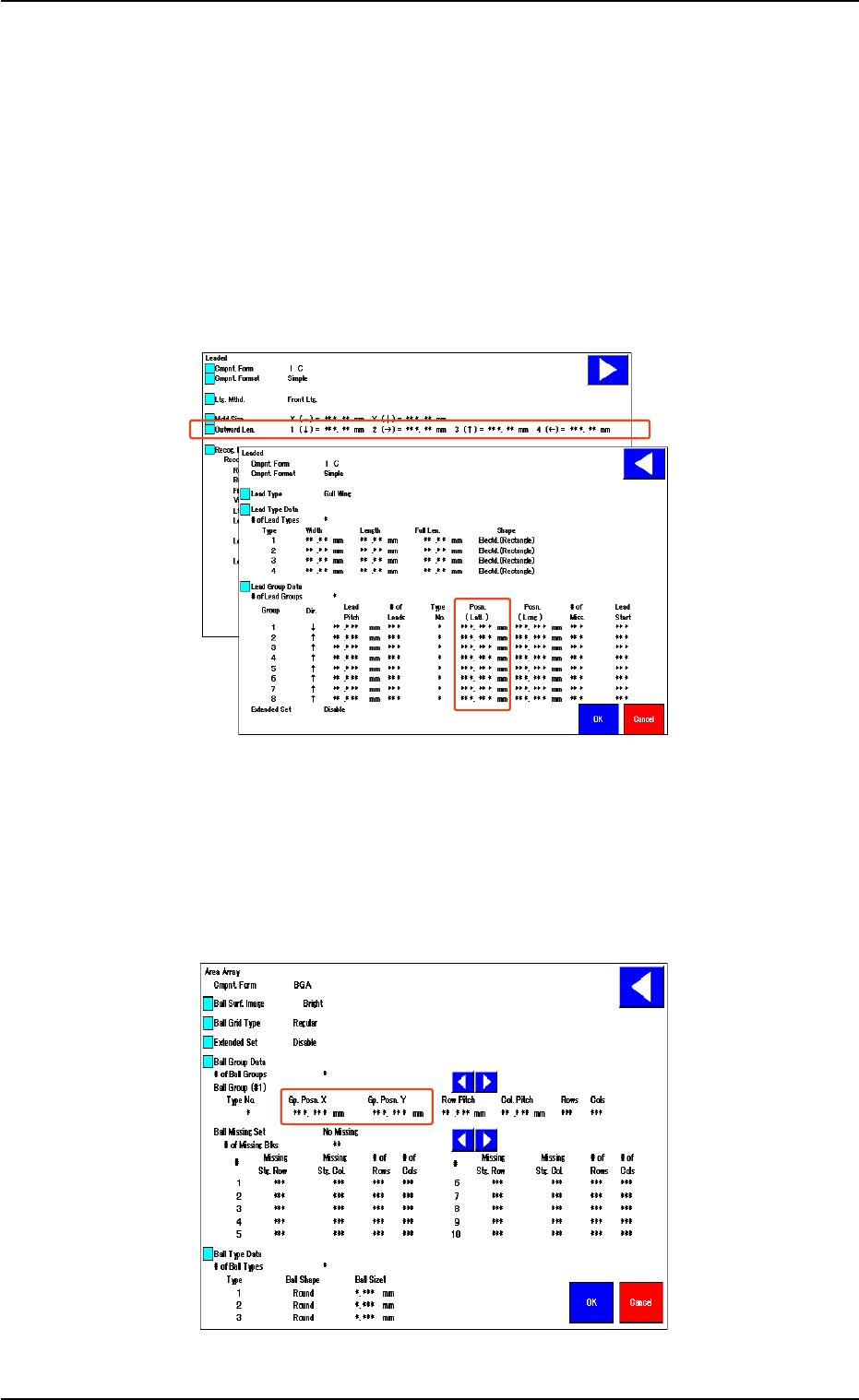
• In the case of "Area Array", verify the following.
When the center of the grids is located at the center of the compo-
nent, verify that "0 (zero)" is obtained for "Gp. Posn. X" and "Gp. Posn.
Y".
Fig. 2F104-14
5.2 Library Teaching
0308-004 6-139

AHB01ESPP
5.2.9 Helpful Hints for Correction & Teaching
When abnormality was found in the output data after the teaching op-
eration on the leaded component (Component Shape: Leaded), follow
the steps below to perform the correction & teaching operation.
••
••
• Mold Size Unconformable to Outward Length Data
When the shape of the mold almost looks like "Round" or the trans-
mitted image of the component stays inside the silhouette of the ir-
regular nozzle, the mold teaching operation cannot be performed cor-
rectly. In this case, follow the steps below.
(1) Correct the mold size and outward length as shown below and align
the graphic with the image.
(2) Follow the operation sequence ([Teach] Button Æ [Correction &
Teach] Button Æ [Lead Teach] Button).
Fig. 2F104-15
••
••
• Unconformable Lead Data
When a connector (shown below) is used and the lead end is not in
conformity with the outward length, the lead teaching operation may
not be performed correctly. In this case, follow the steps below.
(1) Correct the outward length as shown below and align it with the lead
end.
(2) Follow the operation sequence ([Teach] Button Æ [Correction &
Teach] Button Æ [Lead Teach] Button).
(3) Reset the corrected outward length to the original one.
Fig. 2F104-16
5.2 Library Teaching
0308-004 6-140
Mold Size
Outward Length