2OM-1075-002.pdf - 第24页
6. Component Placeable Range Unit: mm Notes: (a) The above figure shows that the vacuum nozzles are not pro- truding from the outer shapes of components. Consult our marketing department or sales agency for de- tails. (b…
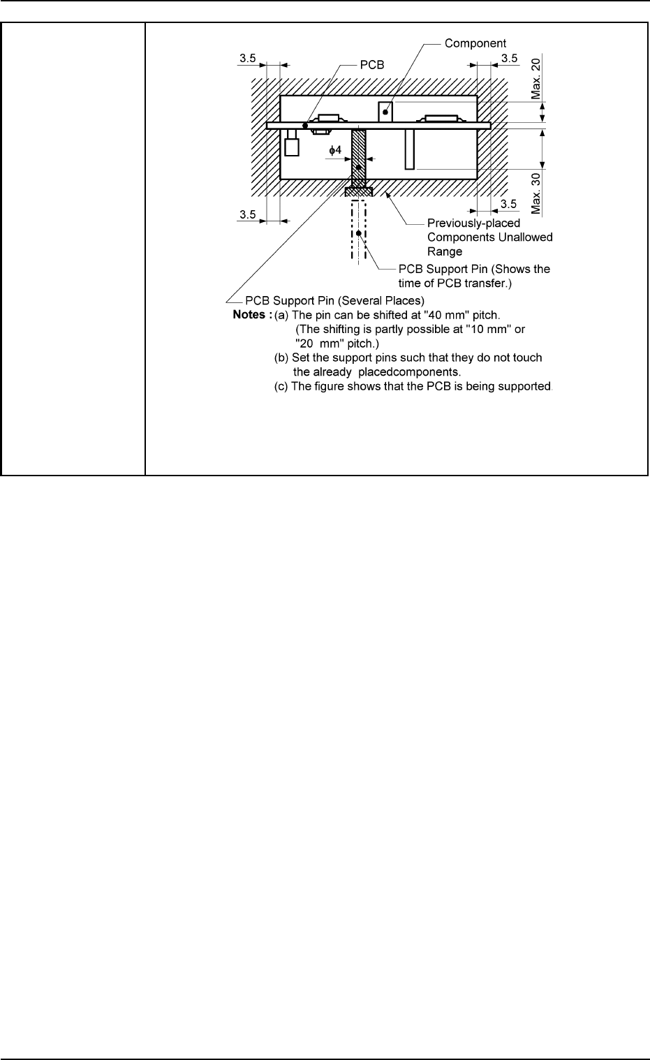
5. Conditions of
P.C.B. before
Placement
Unit: mm
Note: The dimensions are for design reference. Leave some room for
the actual setting.
0206-003 1-6 AHB01ESPP
2. Specifications
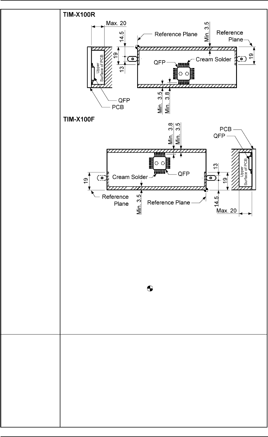
6. Component
Placeable
Range
Unit: mm
Notes: (a) The above figure shows that the vacuum nozzles are not pro-
truding from the outer shapes of components.
Consult our marketing department or sales agency for de-
tails.
(b) Components cannot be placed in the shadowed areas.
(c) Components cannot be placed in the range (0.5 mm) around
the opening such as a hole.
(d) The center of the
mark is the reference point.
The reference point and plane differ depending on the con-
tents of the specifications. There is no change in the distance
between the reference point and the P.C.B. stopper.
Consult our marketing department or sales agency for de-
tails.
7. Placement Time Chip-Type Components: Approx. 0.6 sec/pc. (Highest Speed)
IC (SOP/QFP) : Approx. 0.6 sec/pc. (Highest Speed)
BGA/CSP/FC : Approx. 0.6 sec/pc. (Highest Speed)
Notes: (a) P.C.B. transition time is not included in the placement time
under optimum conditions.
(b) When the accuracy of component placement is "±0.04
mm", the placement time becomes "0.77 seconds per
component".
(c) The placement time changes depending on feeder types
and requirements for component placement. Consult our
marketing department or sales agency for details.
2. Specifications
0206-002 1-7 AHB01ESPP
8. Vacuum Nozzle Approx. 1.5 sec/point (under optimum conditions)
Change Time
9. P.C.B. Transition Approx. 4.0 seconds (under optimum conditions)
Time
10. Unit of X/Y 0.01 mm (Designation of Placement Coordinates)
Beam (Resolution: 0.001 mm/pulse)
Movement
11. Placement 0° to 359°59' (1' pitch)
Direction and (Resolution of Rotation: 0.006°/pulse)
Unit
12. Placement Chip-Type Components : ±0.07 mm
Accuracy IC (SOP, QFP, PLCC) : ±0.04 mm
BGA/CSP : ±0.04 mm
13. Applicable
• Tape Feeders
Feeders
• Stick Feeders (Vibratory Type)
Note: Feeders can be installed on only Feeder Bases #3 and #4.
(Standard Specifications).
• Multi-Layer Tray Feeders (Option)
Note: Feeders can be installed on only Feeder Base #2. (Standard
Specifications).
14. Feeder Feeders can be installed on "1 to 4" positions as shown in the figure
Allocation below.
Consult our marketing department or sales agency for feeder installation
and combination.
Note: Stick feeders (vibratory) can be installed on only Feeder Bases #3
and #4 (Standard Specifications). Installation on a feeder base other
than Feeder Bases #3 and #4 is optional.
2. Specifications
Rear Side of Machine
Front Side of Machine
Feeder Base #3
Feeder Base #1
432
to 401
Feeder Base #2
(Space for Option)
Feeder Base #4
332
to 301
101
to 132
0206-002 1-8 AHB01ESPP