2OM-1075-002.pdf - 第238页
AHB01ESPP 2.2.1 "Machine" T ab The corresponding tab sheet enables the operator to perform a manual axis operation on the devices (axes) of the machine. • • • • • Sheet Layout When the "Machine" tab i…
AHB01ESPP
2.2 "Manual Axis Opn." Tab
The corresponding tab sheet enables the operator to perform an manual
axis operation on the selected device.
• Sheet Layout
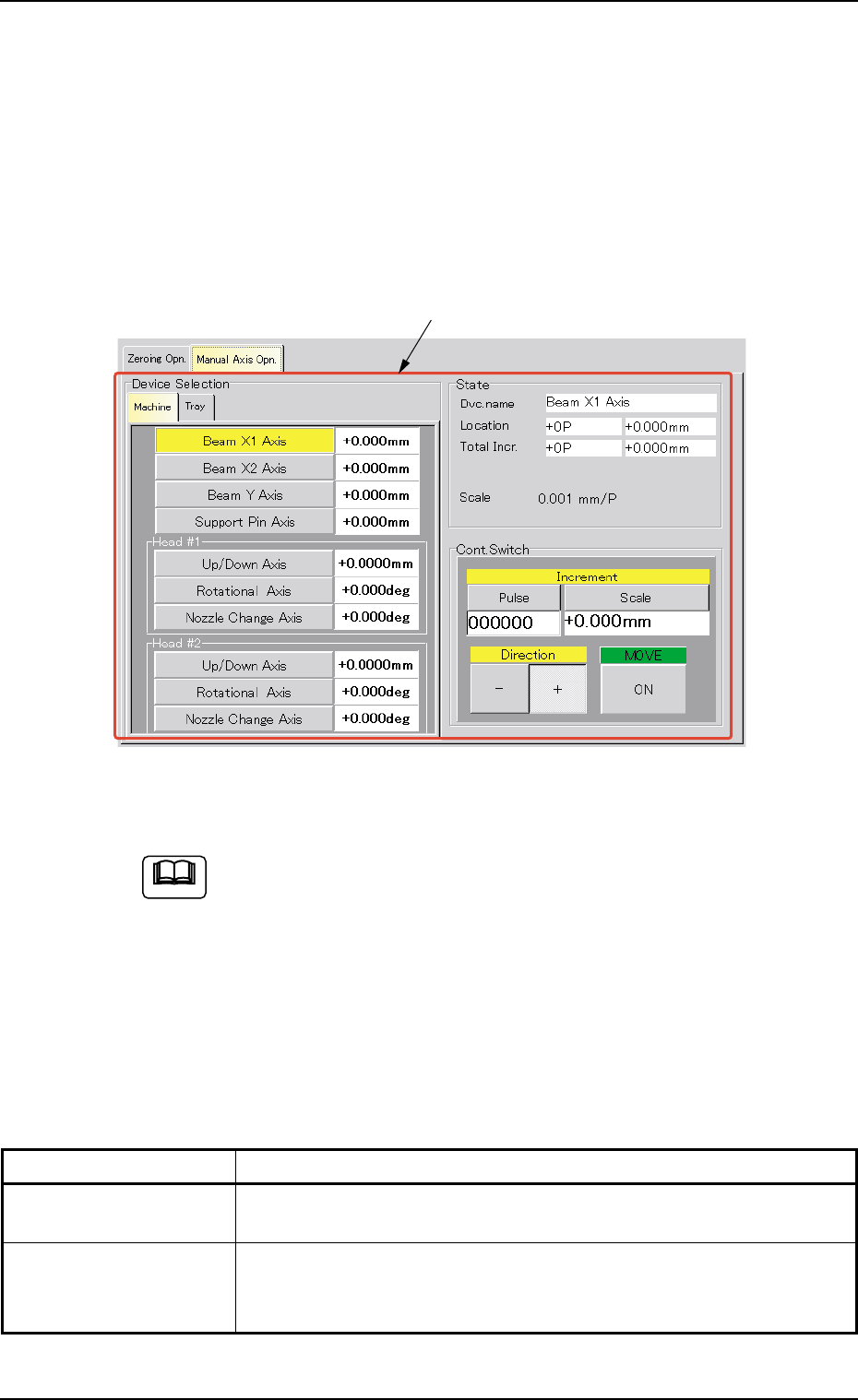
When the "Manual Axis Opn." tab is pressed in the "MNL OPN." window
(submenu), the following tab sheet appears inside the window.
Fig. 2F5 "Manual Axis Opn." Tab Sheet
(Provided with Multi-Layer Tray Feeder 2)
The tab sheet may look different, depending on which options
are selected.
• Sheet Composition
*1 Tabs and Tab Sheets
The "Manual Axis Opn." tab sheet is provided with the following 2
tabs. When a tab is pressed, the corresponding tab sheet appears.
Table 2F2
Tabs Description
Machine The corresponding tab sheet enables the operator to perform a
manual axis operation on the devices (axes) of the machine.
Tray This is an optional function.
Refer to the instruction manual of the multi-layer tray feeders for
details.
0308-004 6-8
2.2 "Manual Axis Opn." Tab
Note
*1
AHB01ESPP
2.2.1 "Machine" Tab
The corresponding tab sheet enables the operator to perform a manual
axis operation on the devices (axes) of the machine.
••
••
• Sheet Layout
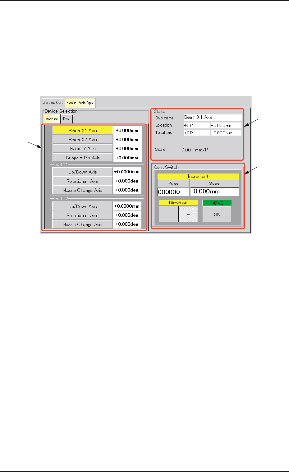
When the "Machine" tab is pressed in the "Manual Axis Opn." tab sheet,
the following tab sheet appears.
Fig. 2F6 "Machine" Tab Sheet
••
••
• Sheet Composition
*1 Device Selection Buttons
The following buttons are provided in this group box.
[Beam X1 Axis] Button
[Beam X2 Axis] Button
[Beam Y Axis] Button
[Support Pin Axis] Button
[Up/Down Axis] Button in "Head #1" Group Box
[Rotational Axis] Button in "Head #1" Group Box
[Nozzle Change Axis] Button in "Head #1" Group Box
[Up/Down Axis] Button in "Head #2" Group Box
[Rotational Axis] Button in "Head #2" Group Box
[Nozzle Change Axis] Button in "Head #2" Group Box
2.2 "Manual Axis Opn." Tab
0308-004 6-9
*1
*2
*3

AHB01ESPP
When a button is pressed, the background color turns yellow, indi-
cating that the device (axis) is selected.
Pressing the button again changes the background color to the origi-
nal one, indicating that the selection is canceled.
Each button has a box on the right side and the current position of
the corresponding device is displayed.
When the machine is in the "PAUSE" mode, no manual axis
operation can be performed on the head.
*2 "State" Group Box
The following information is displayed.
Dvc. name : Displayed is the name of the selected device.
Location : The current position is expressed by the number of
pulses "---P" and the distance "---mm" or the angle
"---°".
When the current position is indefinite, "---" appears
in each box.
Total Incr. : The total increments (travel) of the selected device
are expressed by the number of pulses "---P" and the
distance "---mm" or the angle "---°".
Scale : Displayed is the resolution of movement.
0.9°/128 P
The following table shows the resolutions and data input
ranges for manual axis operation of each device.
Table 2F3
Devices Resolutions Data Input Ranges
Beam X1 Axis 0.001 mm/p ±999999 (P)
Beam X2 Axis 0.001 mm/p ±999999 (P)
Beam Y Axis 0.001 mm/p ±999999 (P)
Support Pin Axis 0.005 mm/p ±999999 (P)
Head #1 Up/Down Axis 0.0025 mm/p ±999999 (P)
Head #1 Rotational Axis 0.006°/p ±999999 (P)
Head #1 Nozzle Change Axis 0.005°/p ±999999 (P)
Head #2 Up/Down Axis 0.0025 mm/p ±999999 (P)
Head #2 Rotational Axis 0.006°/p ±999999 (P)
Head #2 Nozzle Change Axis 0.005
°/p ±999999 (P)
Note
0308-004 6-10
2.2 "Manual Axis Opn." Tab
Note