2OM-1075-002.pdf - 第34页
38. Measured [Measurement Condition] Noise V alue • Measuring Position Position 1 m away and 1.6 m in height from the machine (Both Front and Rear Sides of Machine) • Noise Measuring Instrument Model: RION NA-60 (Range A…
32. Air Pressure Supply 0.49 to 0.69 MPa (5 to 7 kgf/cm
2
)
Pressure
Set 0.4 MPa (4.1 kgf/cm
2
)
Pressure Note: The air pressure of 0.4 MPa (4.1 kgf/cm
2
) or more is
required during operation.
• Use the following dry and clean air.
Moisture : Dew Point -17°C or lower (Atmospheric Pressure)
Oil : 0.1 mg/m
3
or less (ANR)
Dust : Solid Material 0.01 µm or less
33. Air Approx. 20 L/min (Standard Condition)
Consumption
34. Vacuum -93 kPa (70 cmHg)
Pressure
35. Environmental Temperature: 20±10°C
Condition Humidity : 30 to 80% (Avoid dew condensation.)
Note : When the ambient temperature rises more than the surface of the
machine, dew may condense under the condition described be-
low.
Note that dew condensation may cause the machine to break down.
Condition of Dew Condensation
Dew may condense when the differences (based on "Humidity
(%)") between the ambient and surface temperatures of the ma-
chine reach the values or more in the table below.
Humidity Differences between Ambient and Surface
(%) Temperatures of Machine
(Ambient Temperature > Surface Temperature)
80 3°C or more
70 6°C or more
60 8°C or more
50 10°C or more
40 14°C or more
30 18°C or more
36. Dimensions Approx. 1,550 (width) × 1,995 (depth) × 1,450 (height) mm
Note: The height becomes 2,100 mm when the light tower is included.
37. Mass 1,670 kg (excluding the feeders )
Note: The mass changes depending on the type of feeders to be installed.
Mass of Options (For Reference)
Name Mass (kg)
Tape Feeder The mass depends on feeder types.
Vibratory Stick Feeder Approx. 6.5/unit
Attachment Approx. 9/unit
Multi-Layer Tray Feeder Approx. 130/unit
Note: The mass related to components is not included.
2. Specifications
0206-003 1-16 AHB01ESPP
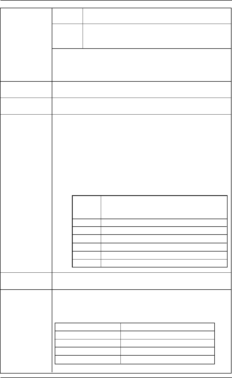
38. Measured [Measurement Condition]
Noise Value • Measuring Position
Position 1 m away and 1.6 m in height from the machine
(Both Front and Rear Sides of Machine)
• Noise Measuring Instrument
Model: RION NA-60 (Range A)
• Requirements for Machine Operation
Test Run Actions: No P.C.B. Transfer, No Component Picks/No Recog-
nition/No Placement, Repetition of Stages 1 and 30
for Multi-Layer Tray Feeder 2, Two 8 mm Tape Feed-
ers activated
Measuring Point *1 *2 *3 *4 *5 *6 *7 *8 Remarks
Measured Noise
69.8 67.1 67.2 68.5 70.2 68.9 68.3 68.4
Background Noise
Value [dB]
(Surroundings)
60.2 [dB]
(Front Side of Machine)
2. Specifications
0206-002 1-17 AHB01ESPP
2. Specifications
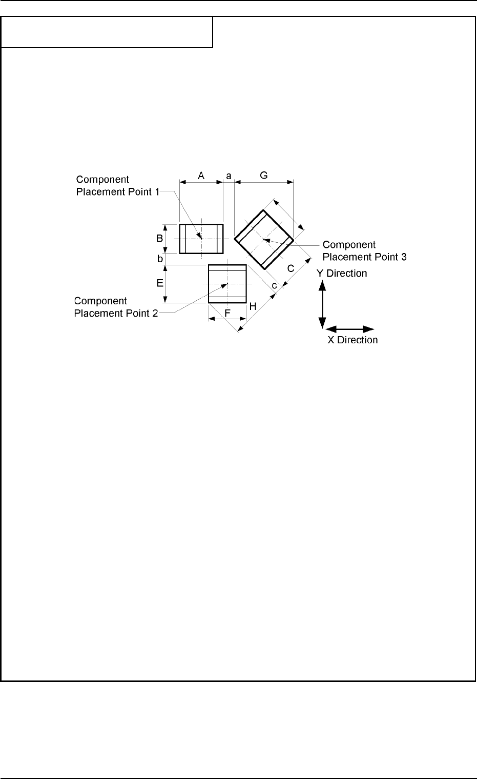
39. Requirements for Component
Placement
(1) Shape of Vacuum Nozzle
When components are to be placed close to the previously-placed components or the
obstacles, the shape of the vacuum nozzle becomes part of the constraint condition.
Refer to "3. List of Nozzle Types" for the shapes of vacuum nozzles.
(2) Adjoining Distances between Components (when the component placement position is
taken into consideration)
Notes: (a) The above figure shows that the vacuum nozzles are not protruding from the
outer shapes of components.
Consult our marketing department or sales agency for details.
(b) "A to H" in the above figure show the maximum dimensions including the varia-
tions in the dimensions of each component. The minimum adjoining distances
(a, b, and c) of each component should be 0.4 mm.
(c) The minimum adjoining placement position data for component placement points
1 and 3 is
"X Direction Data = (A + G)/2 + Min. 0.4 mm"
(The Y direction data is not related.)
(d) The minimum adjoining placement position data for component placement points
1 and 2 is
"Y Direction Data = (B + E)/2 + Min. 0.4 mm"
(The X direction data is not related.)
(e) See the above figure and obtain the minimum adjoining placement position data
for Component Placement Points 2 and 3.
0206-002 1-18 AHB01ESPP