2OM-1075-002.pdf - 第214页
AHB01ESPP [Conveyor Width Origin] Button Select the [Conveyor Width Origin] button and press the [ON] button (entitled "MOVE"). After that, press the [ENABLE] but- ton on the operation panel in 2 seconds. The c…
AHB01ESPP
7.3 "PCB Support Pins Set-up Mode" Tab
The corresponding tab sheet enables the operator to set the environ-
mental condition required to specify the positioning of the P.C.B. sup-
port pins.
••
••
• Sheet Layout
When the "PCB Support Pins Set-up Mode" tab is pressed in the "PRGM.
CHG." window (submenu), the following tab sheet appears inside the
window.
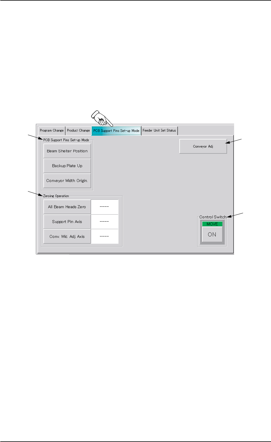
Fig. 2E43 "PCB Support Pins Set-up Mode" Tab Sheet
••
••
• Sheet Composition
*1 "PCB Support Pins Set-up Mode" Group Box
The following buttons are provided in this group box.
[Beam Shelter Position] Button
Select the [Beam Shelter Position] button and press the [ON]
button (entitled "MOVE"). After that, press the [ENABLE] but-
ton on the operation panel in 2 seconds. The X/Y beam es-
capes back to the rear side.
[Backup Plate Up] Button
Select the [Backup Plate Up] button and press the [ON] but-
ton (entitled "MOVE"). After that, press the [ENABLE] button
on the operation panel in 2 seconds. The backup plate starts
moving up.
7.3 "PCB Support Pins Set-up Mode" Tab
*1
*4
*2
*3
0206-003 5-51

AHB01ESPP
[Conveyor Width Origin] Button
Select the [Conveyor Width Origin] button and press the [ON]
button (entitled "MOVE"). After that, press the [ENABLE] but-
ton on the operation panel in 2 seconds. The conveyor width
widens to the origin position (fully opened condition).
*2 "Zeroing Operation" Group Box
The following buttons are provided in this group box.
[All Beam Heads Zero] Button
Select the [All Beam Heads Zero] button and press the [ON]
button (entitled "MOVE"). After that, press the [ENABLE] but-
ton on the operation panel in 2 seconds. The X/Y Beam is
zeroed.
[Support Pin Axis] Button
Select the [Support Pin Axis] button and press the [ON] but-
ton (entitled "MOVE"). After that, press the [ENABLE] button
on the operation panel in 2 seconds. The backup plate is ze-
roed.
[Conv. Wid. Adj. Axis] Button
Select the [Conv. Wid. Adj. Axis] button and press the [ON]
button (entitled "MOVE"). After that, press the [ENABLE] but-
ton on the operation panel in 2 seconds. The conveyor width
is zeroed.
*3 [Conveyor Adj] Button
When this button is pressed, the "Conveyor Adjustment" window
opens, enabling the operator to adjust the conveyors for the motor
operations.
*4 Control Switch
Select a button in the "PCB Support Pins Set-up Mode" group box
(*1) or the "Zeroing Operation" group box (*2) and press the [ON]
button (entitled "MOVE"). Press the [ENABLE] button on the opera-
tion panel in 2 seconds. The function related to the button is acti-
vated.
Refer to "Section 3 Program Change Operation" for the po-
sitioning procedure of P.C.B. support pins.
7.3 "PCB Support Pins Set-up Mode" Tab
Note
01 12-002 5-5 2
AHB01ESPP
7.3.1 "Conveyor Adj" Window
This window enables the operator to activate the conveyor motors.
••
••
• Sheet Layout
When the [Conveyor Adj] button is pressed in the "PCB Support Pins
Set-up Mode" tab sheet, the following window appears.
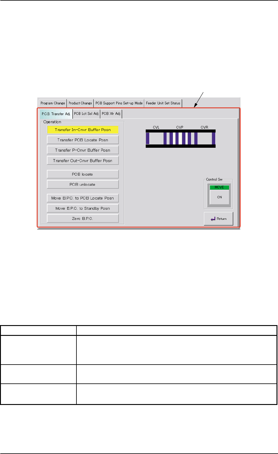
Fig. 2E44 "Conveyor Adj" Window
••
••
• Sheet Composition
*1 Tabs and Tab Sheets
The "Conveyor Adj" window is provided with the following 3 tabs.
When a tab is pressed, the corresponding tab sheet appears.
Table 2E9
Tabs Description
P.C.B. Transfer Adj. The corresponding tab sheet enables the operator to conduct a per-
formance test according to the data specified in the "Xfr Prmtr Adj"
tab sheet.
PCB Lct Sol Adj The corresponding tab sheet enables the operator to activate the
P.C.B. locate solenoid.
PCB Xfr Adj The corresponding tab sheet enables the operator to activate the
conveyor motors.
7.3 "PCB Support Pins Set-up Mode" Tab
*1
0206-002 5-53