2OM-1075-002.pdf - 第18页
1. Features This machine is capable of recognizing various types of electrical com- ponents and precisely place them on a P .C.B. This latest and multi-functional mounter is provided with advanced tech- nologies such as …

0107-001 1-B AHB01ESPP

1. Features
This machine is capable of recognizing various types of electrical com-
ponents and precisely place them on a P.C.B.
This latest and multi-functional mounter is provided with advanced tech-
nologies such as small and light multi-heads, a fly nozzle change func-
tion, a fly recognition function, and X/Y-axis linear motor driving and
equipped with easy-to-operate user interfaces, making it possible to
maintain high total productivity.
Table 2A1
New Mechanism Features
X/Y-Axis Linear Motor • Y-Axis Twin Driving System
Driving • X/Y Beam High-Speed Movement
• Long-Term Maintenance-Free Structure
Multi-Heads • Small and Light Servomotors
• Highly Accurate Placement Angle (Z) Correction
• Simultaneous Pick-Up Enabled by Independent Driving Heads
(not restricted by feeder pitches)
Fly Nozzle Change • Nozzle Change Function Implemented during Head Movement
Function
Fly Recognition Function • Component Recognition Performed during Head Movement
Highly Accurate Image • Highly Accurate Image Recognition System
Recognition Function • Stabilization of Component Pick-Up and Placement by Real
Time Automatic Correction
New Mobile Tape Feeder • Attachment/Detachment Possible during Automatic Operation
• LED Flashing (Warning) at Component Shortage
User Interfaces • Programs based on Windows 2000
• Improvement of Operativeness (Combination of Touch Screen
and Keyboard/Pointing Device)
• High-Speed Data Communication on Ethernet Network
1. Features
0308-002 1-1 AHB01ESPP
2. Specifications
2. Specifications
Table 2A2
0206-003 1-2
AHB01ESPP
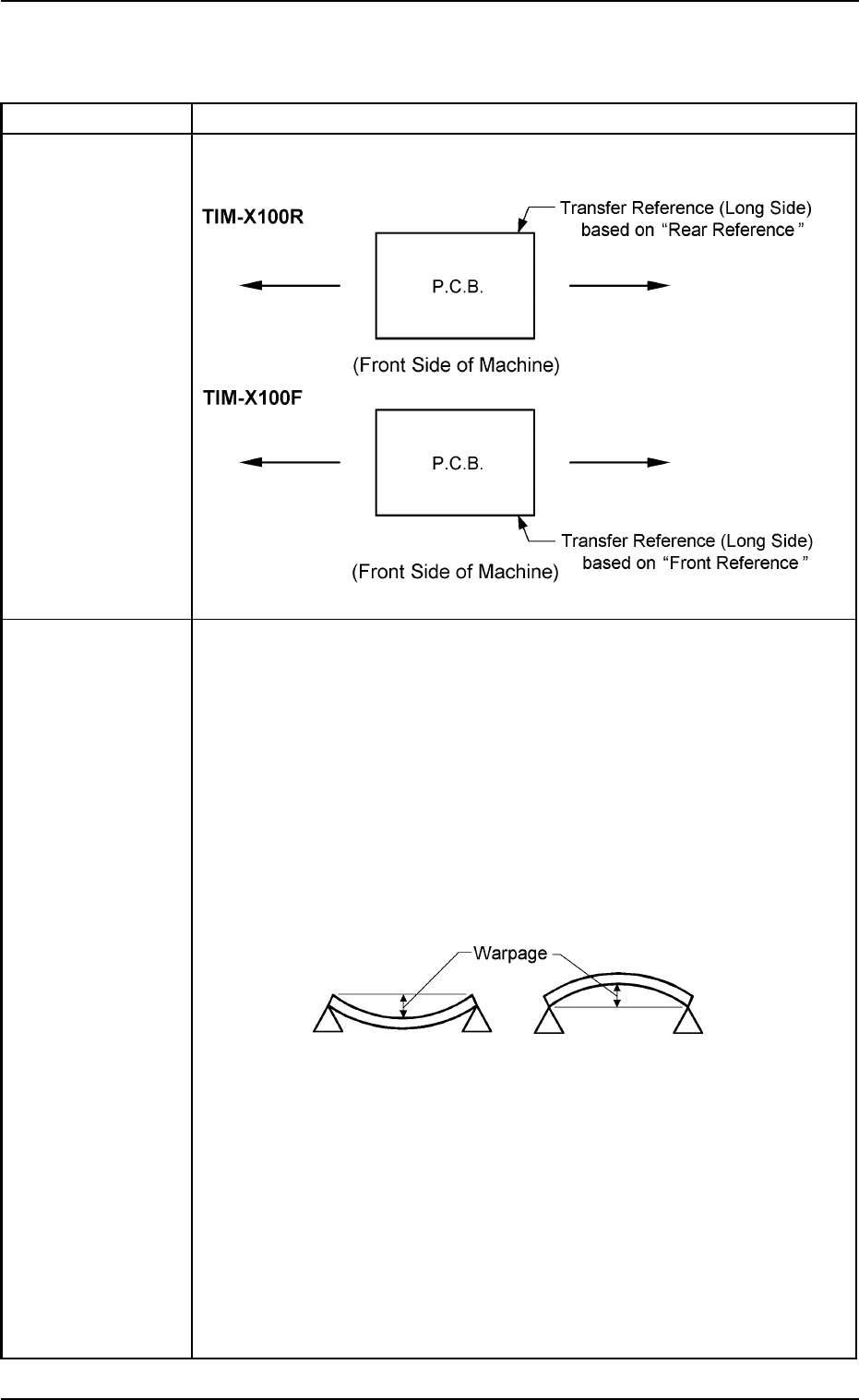
1. Model Name TIM-X100R TIM-X100F
2. P.C.B. Flow P.C.B. Flow Direction: From Left to Right or vice versa (Easy-to-Change
Direction and Function)
Transfer
Reference
3. Applicable P.C.B. Size : 50 × 50 to 330 × 250 mm
(Four Corners: R1 to R1.5 mm)
Thickness : 0.3 to 2.5 mm
Warpage : The following two requirements must be met.
• 0.2 mm or less per 50 mm (unit length)
Example : The warpage must be 0.8 mm or less when
the P.C.B. size is 200 mm.
• Max. 1.0 mm
Example : The warpage must be 1.0 mm or less when
the P.C.B. size exceeds 250 mm.
Mass : Max. 2 kg (Completed P.C.B.)
Material : Glass Epoxy
Ceramic
(Consult our marketing department or sales agency for de-
tails.)
Notes: (a) Consult our marketing department or sales agency for hypo-
chromic glass epoxy.
(b) A test is required for greater warpage, depending on the ma-
terial and shape of the P.C.B. being used.