2OM-1075-002.pdf - 第246页
AHB01ESPP [Recognition Algorithm] Button [Fiducial Mark Image] Button [Fiducial Mark Level] Button [Fiducial Mark Theta] Button [Set Mark] Button [Gain] Button [Level] Button Refer to "3.2.1 V arious Data Settings f…
AHB01ESPP
3.2 "P.E.C. Recog Test" Tab
The corresponding tab sheet enables the operator to make a test on the
P.E.C. recognition (fiducial) marks.
• Sheet Layout
When the "P.E.C. Recog Test" tab is pressed in the "DVC. TEST" win-
dow (submenu), the following tab sheet appears.
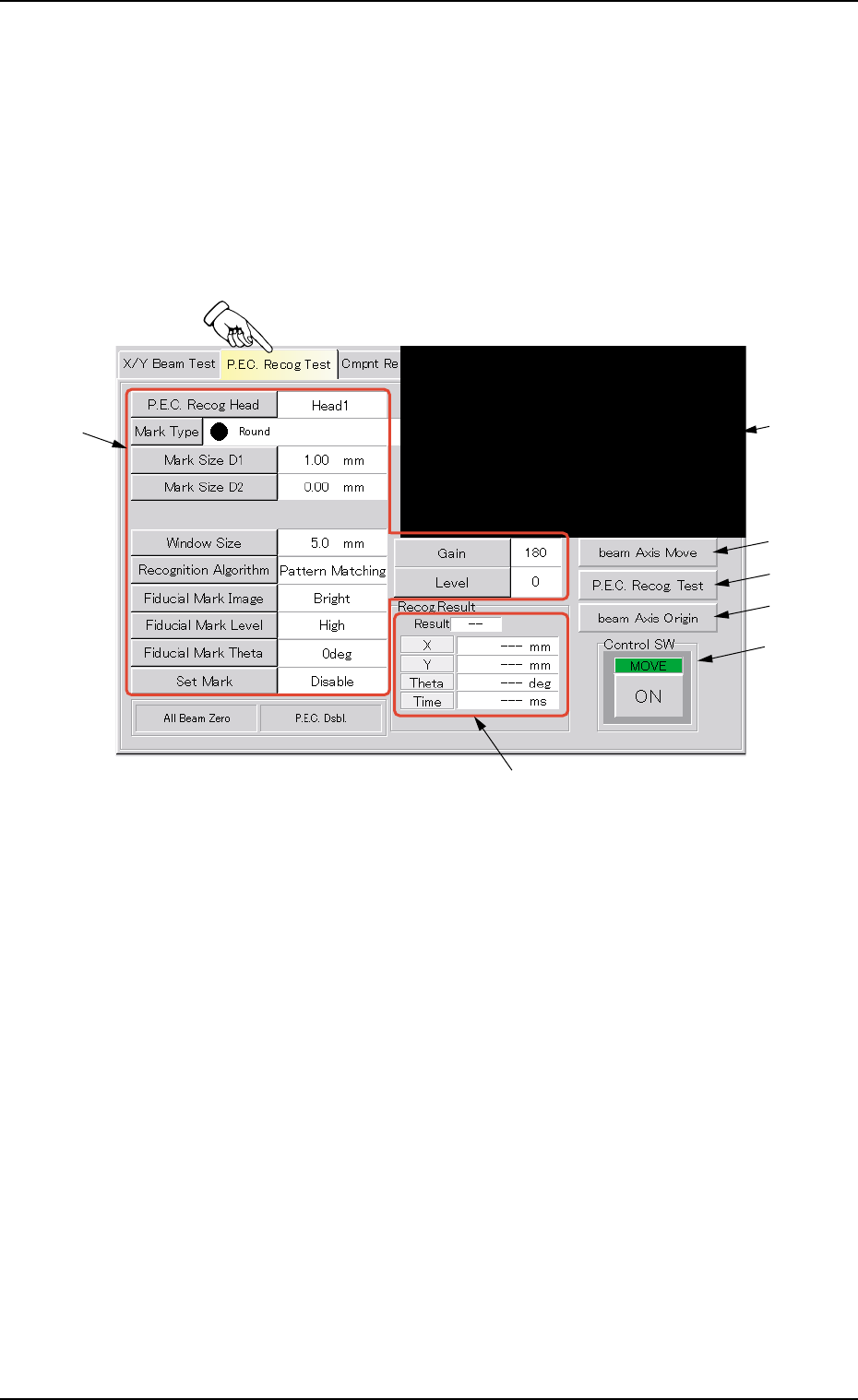
Fig. 2F8 "P.E.C. Recog Test" Tab Sheet
• Sheet Composition
*1 Recognized Image
The image of the recognized P.C.B. is displayed.
When this area is pressed, the image of the recognized component
disappears.
*2 Buttons for P.E.C. Recognition Test Data Settings
When one of the following buttons is pressed, the corresponding
window for parameter settings opens, enabling you to specify each
parameter for the P.C.B. recognition marks (fiducial marks).
[P.E.C. Recog Head] Button
[Mark Type] Button
[Mark Size D1] Button
[Mark Size D2] Button
[Window Size] Button
0206-003 6-13
3.2 "P.E.C. Recog Test" Tab
*2
*3
*1
*4
*5
*7
*6

AHB01ESPP
[Recognition Algorithm] Button
[Fiducial Mark Image] Button
[Fiducial Mark Level] Button
[Fiducial Mark Theta] Button
[Set Mark] Button
[Gain] Button
[Level] Button
Refer to "3.2.1 Various Data Settings for P.E.C. Recognition Marks"
for the detailed information on each parameter.
*3 [beam Axis Move] Button
When pressed, this button moves the X/Y beam.
*4 [P.E.C. Recog Test] Button
When pressed, this button sets a P.E.C. recognition test ready for
being made.
*5 [beam Axis Origin] Button
When pressed, this button zeroes the X/Y beam.
*6 "Recog Result" Group Box
Displayed are the coordinates that represent how far the fiducial
mark shifted from the correct position when a recognition test was
performed.
*7 "Control SW" Group Box
Press the [P.E.C. Recog Test] button and the [ON] button (entitled
"MOVE"). After that, press the [ENABLE] button in two seconds.
The P.E.C. recognition test is conducted.
Refer to "3.2.2 Procedure for P.E.C. Recognition Test" for the
detailed information on how to make a P.E.C. recognition test.
0206-003 6-14
Note
3.2 "P.E.C. Recog Test" Tab
AHB01ESPP
3.2.1 Various Data Settings for P.E.C. Recognition Marks
Refer to "2.4 Placement Feeder Location Data" in "Section 2
Pattern Program" of "Vol. 3: Programming and Machine Data"
for the description of each parameter.
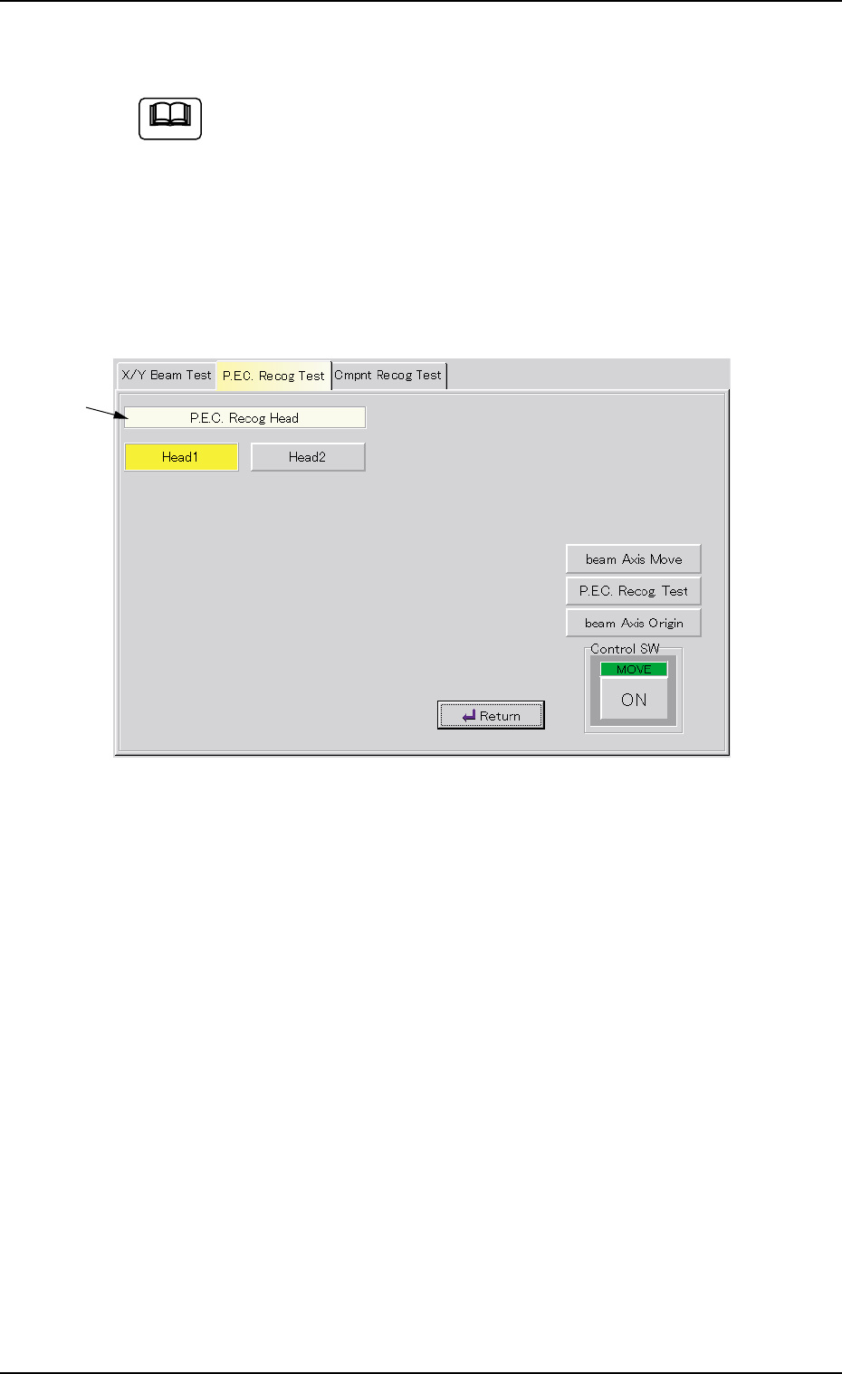
P.E.C. Recog Head
(1) When the [P.E.C. Recog Head] button is pressed in the "P.E.C. Recog
Test" tab sheet, the following sheet appears as follows.
Fig. 2F9
(2) Press the [Head1] or the [Head2] button.
The selected button turns yellow, indicating that the corresponding
head for P.E.C. recognition is selected.
(3) When the [Return] button is pressed, the "P.E.C. Recog Test" tab
sheet appears.
0206-003 6-15
3.2 "P.E.C. Recog Test" Tab
*1
Note