2OM-1075-002.pdf - 第150页
AHB01ESPP "CAMERA" : It is required to specify a camera ID. When the [CAMERA] button is selected, the [CAMERA ID] button appears under the se- lected button. Every time the [CAMERA ID] button is pressed, the la…
AHB01ESPP
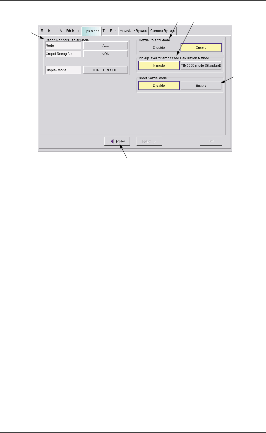
Fig. 2E13 "Opn. Mode" Tab Sheet
*7 Recog Monitor Display Mode
It can be specified how to display the results of recognition such as
P.E.C. and component recognition functions.
Mode
Specify the recognition mode which the displayed result should
be based on.
Every time the right button is pressed, the label changes in scroll-
ing such as "ALL" Æ "DEVICE" Æ "P.C.B.".
"ALL" : When this is selected, the results of the com-
ponent and P.E.C. recognition operations are
regarded as object items to be displayed.
"DEVICE" : When this is selected, the results of the com-
ponent recognition operation are regarded as
object items to be displayed.
"P.C.B." : When this is selected, the results of the P.E.C.
recognition operation are regarded as object
items to be displayed.
Cmpnt Recog Sel
When the results of the component recognition operation are
regarded as object items to be displayed (when [ALL] or [DE-
VICE] is selected for "Mode"), it is required to specify the condi-
tion (requirements) for the component recognition.
Every time the right button is pressed, the label changes in scroll-
ing such as "NON" Æ "CAMERA" Æ "PARTS" Æ "FEEDER".
"NON" : There is no condition (requirements) for com-
ponent recognition.
0308-004 5-21
3.3 "Opn. Mode" Tab
*7
*8
*11
*10
*9

AHB01ESPP
"CAMERA" : It is required to specify a camera ID.
When the [CAMERA] button is selected, the
[CAMERA ID] button appears under the se-
lected button.
Every time the [CAMERA ID] button is pressed,
the label of the right button changes in scroll-
ing such as "CAM-A1" Æ "CAM-B1" Æ "CAM-
A2" Æ "CAM-B2" Æ "CAM-M1" Æ "CAM-M2".
"PARTS" : It is required to specify a component ID.
When the [PARTS] button is selected, the
[PARTS ID] button appears under the selected
button.
When the [PARTS ID] button is pressed, the
"PARTS ID" edit window opens. Enter the com-
ponent ID to be specified.
"FEEDER" : It is required to specify a feeder No.
When the [FEEDER] button is selected, the
[FEEDER No.] button appears under the se-
lected button.
When the [FEEDER No.] button is pressed,
the "FEEDER No." edit window opens. Enter
the feeder No. to be specified.
Display Mode
Set the condition to display the recognition results of the compo-
nent recognition.
Every time the right button is pressed, the label changes in scroll-
ing such as "NON" Æ "+LINE" Æ "+LINE + RESULT".
[NON] : Only the outline of the recognized component is
displayed.
[+LINE] : The outline of the recognized component and a
crosshair are displayed.
[+LINE+RESULT] : The outline of the recognized component, a
crosshair, and the result of the recognition (the
coordinates of the crosshair center) are dis-
played.
3.3 "OPN. Mode" Tab
0308-004 5-22

AHB01ESPP
*8 "Nozzle Polarity Mode" Group Box
When the same library data is used for both Sides A and B, it can be
determined whether or not the polarity nozzles should be used.
[Enable] Button: Production becomes possible, using the same
library data.
[Disable] Button: Production becomes impossible, using the same
library data.
It is required to create the library data separately
and use the data for each production.
Default: [Disable] Button Selected
(a) When the polarity nozzles are used and the same com-
ponents are arranged on both Sides A (Rear Beam)
and B (Front Beam) through component picks, the
same library data may not be used without any modi-
fication. Therefore, it is required to select this nozzle
polarity mode.
(b) Actions taken to pick up a polarity component from
the rear side
A component is picked up after the Z axis of the head
is rotated 180 degrees and it is recognized and placed
as "Component to be recognized with the movable
camera Æ Component picked up from the front side
(the head rotated back by 180 degrees after the
pickup)" or "Component to be recognized with the fixed
camera Æ Component picked up from the rear side".
*9 "Pickup level for embossed Calculation Method" Group Box
The [Ix mode] or the [TIM5000 mode (Standard)] button can be se-
lected to determine the calculation method of the embossed pickup
level.
[Ix mode] Button: The calculation method for TIM-X100 is used.
[TIM5000 mode (Standard)] Button:
The calculation method for the TIM-5000 series
is used.
Default: [Ix mode] Button Selected
There is a difference in the pickup actions (the descending
positions at component picks) for the components (Thick-
ness T
=
Thickness (t)) on the embossed tape between
TIM-X100 and TIM-5000 series.
Therefore, an error such as "excessive pushing" occurs
when the descending position is not specified according to
the selected data.
3.3 "OPN. Mode" Tab
0308-001 5-22-1
Note
Note