2OM-1075-002.pdf - 第50页
1. Outline of Actions 1 . 1 P .C.B. T ransfer and Positioning The explanation in this session is based on the following requirements. P .C.B. T ransfer Direction : L Æ R P .C.B. Positioning Reference : Rear Left P .C.B. …

0107-001 2 -B AHB01ESPP
1. Outline of Actions
1.1 P.C.B. Transfer and Positioning
The explanation in this session is based on the following requirements.
P.C.B. Transfer Direction : L Æ R
P.C.B. Positioning Reference : Rear Left
P.C.B. Positioning Method : "PRI PCB STR"
(a) The settings for "P.C.B. Transfer Direction" and "P.C.B.
Positioning Method" can be changed.
Refer to "2.2.2 "P.C.B. Transfer Mode Setup" Tab" in "Sec-
tion 5" of "Vol. 3: Programming and Machine Data" for de-
tails.
(b) The P.C.B. positioning reference is factory-specified upon
shipment. It is impossible to change the setting.
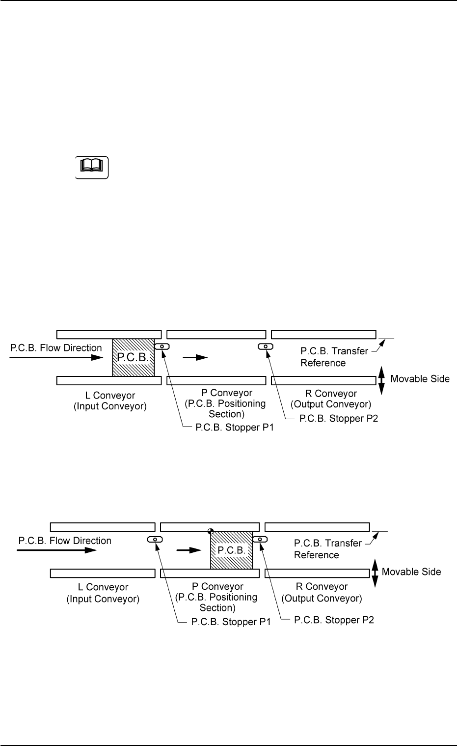
(1) The P.C.B. transferred from the input machine onto the L conveyor
is carried to the position of P.C.B. Stopper P1. (Standby Position)
Fig. 2B1
(2) P.C.B. Stopper P1 descends and the P.C.B. at the standby position
is transferred to P.C.B. Stopper P2.
Fig. 2B2
1.1 P.C.B. Transfer and Positioning
01 12-002 2-1 AHB01ESPP
Note
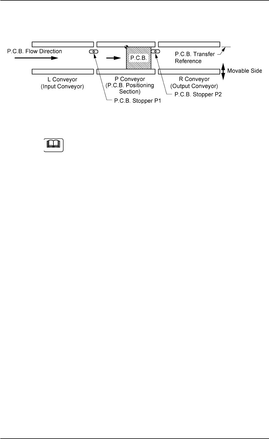
(3) The P.C.B. is clamped by the clamping plate and the pusher on the
P.C.B. positioning section.
Fig. 2B3
The reference pin for positioning is aligned with the P.C.B. hole
position to position the P.C.B.’s.
The sequence is determined as follows.
Backup Plate Upward Movement
(Stop at the place where the clearance between the P.C.B. and
the chute is "0.5 mm")
Clamp Plate Upward Movement + Backup Plate Upward Move-
ment
Positioning Completed
0206-003 2 -2
AHB01ESPP
1.1 P.C.B. Transfer and Positioning
Note