2OM-1075-002.pdf - 第97页
4. 2 Component Placement T est Place an actual component on the P .C.B. and confirm that the compo- nent can be placed without any hindrance. When the component cannot be placed accurately on the specified po- sition, co…
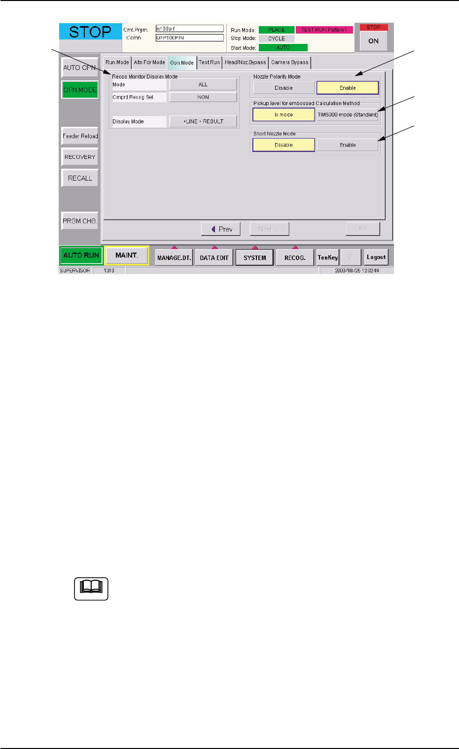
Fig. 2C13 "Opn. Mode" Tab Sheet (Second Page)
Confirmation and Setting of Recog Monitor Display Mode
Confirm or specify the parameters for "Recog Monitor Display Mode"
(*6).
Confirmation and Setting of Nozzle Polarity Mode
Confirm or specify the parameters for "Nozzle Polarity Mode" (*7).
Confirmation and Setting of Pickup level for embossed Cal-
culation Method
Confirm or specify the parameters for "Pickup level for embossed
Calculation Method" (*8).
Confirmation and Setting of Short Nozzle Mode
Confirm or specify the parameters for "Short Nozzle Mode" (*9).
Refer to "3.3 "Opn. Mode" Tab" in "Section 5" for details.
4.1 Setting of Operation Mode
*6
*7
*8
*9
0308-002 3-19 AHB01ESPP
Note

4.2 Component Placement Test
Place an actual component on the P.C.B. and confirm that the compo-
nent can be placed without any hindrance.
When the component cannot be placed accurately on the specified po-
sition, correct the pattern program.
4.2 Component Placement Test
0206-001 3-20 AHB01ESPP

Section 4
Navigation on Touch Screen
0308-002 4-A AHB01ESPP
This section describes the basic items to be understood for
proper touch screen operations.