2OM-1075-002.pdf - 第375页
AHB01ESPP T able 2F17 Component Shape Example of Graphic Representation Displayed Parameters BGA (Normal) A : Mold size X [mm], Y [mm] B : Component Center Center of Mold Size X, Y C : Each Ball Data Diameter : Ball Diam…
AHB01ESPP
(1) Graphical Representation
The following shows the relation between the component library data
and the graphical representation and the coloring for each individual
component shapes.
The graphics related to the parameters to be edited are expressed
in yellow in the data edit window.
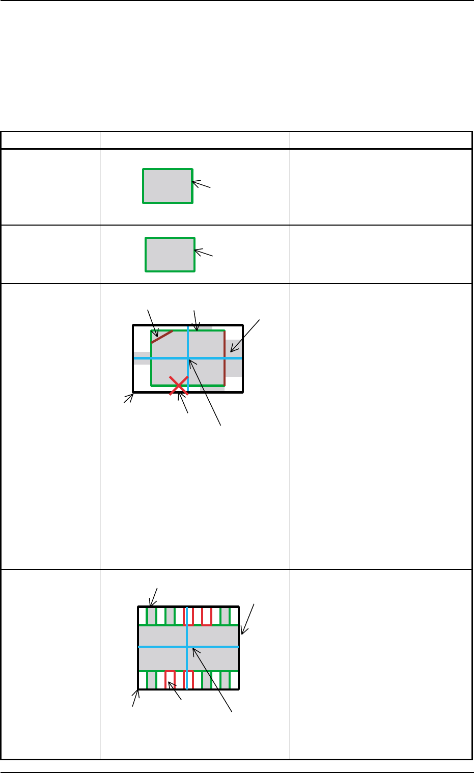
Table 2F16
Component Shape Example of Graphic Representation Displayed Parameters
Cylindrical A: Mold size X [mm], Y [mm]
Square A: Mold size X [mm], Y [mm]
Deformed A: Mold size X [mm], Y [mm]
B: Outward length 1 [mm] through
4 [mm]
C: Component Center
Center of Outward Length
D: Each Corner’s Dimensions X, Y
Note: When "No Detection" is set in
the "Shape" text box in the
"Corner Data" tab sheet, the
corner is expressed in gray.
When "Straight" is set, the cor-
ner is not displayed.
E: Each Edge Detection Posn X [mm],
Y [mm]
This appears only when
"Convexoconcave" is set in the
"Shape" text boxes in the "Edge Data"
tab sheet.
F: Each Edge
This appears in dark red only when
"No Detection" is set in the "Shape"
text boxes in the "Edge Data" tab
sheet.
Leaded
IC
Connector
Other Leaded
5.2 Library Teaching
0308-004 6-142
A: Mold size X [mm], Y [mm]
B: Outward length 1 [mm] through
4 [mm]
C: Component Center
Center of Outward Length
D: Each Lead Data
Width = Lead Width
Height = Lead Length and
Full Lead Length
Position = Calculated based on the
lead group data
E: Missing Lead Data
Calculated based on the lead group
data
A (Green)
A (Green)
A (Green)
C (Light Blue)
E (Red)
B (White)
D (Violet)
F (Dark Red)
D (Green)
A (Green)
B (White)
E (Red)
C (Light Blue)
AHB01ESPP
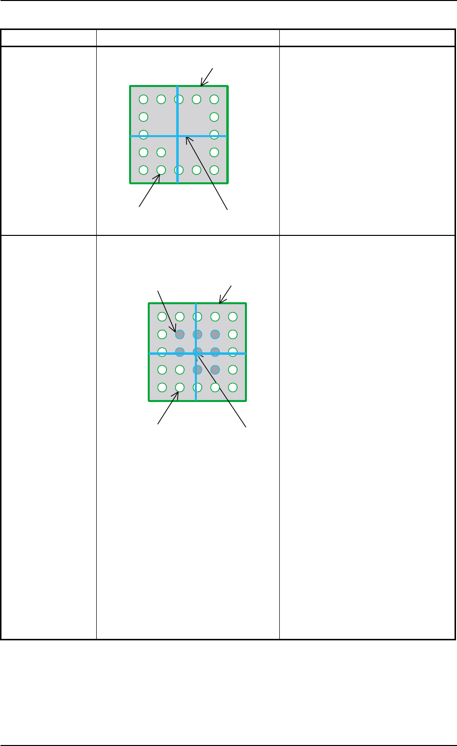
Table 2F17
Component Shape Example of Graphic Representation Displayed Parameters
BGA (Normal) A: Mold size X [mm], Y [mm]
B: Component Center
Center of Mold Size X, Y
C: Each Ball Data
Diameter : Ball Diameter
Position : Each Ball Group
Calculated based on
each ball group data
During Data Editing A: Mold size X [mm], Y [mm]
B: Component Center
Center of Mold Size X, Y
C: Each Ball Data
Diameter: Ball Diameter
Position : Calculated based on
each ball group data
Yellow : Balls in Object Group for
Editing
Green : Balls in Other Block
(block other than object
one for editing)
D: Each Missing Ball Data
Diameter: Ball Diameter
Position : Calculated based on
each ball group data
Light Blue :
Balls in Object Missing
Block for Editing
Red : Balls in Other Missing
Block (missing block
other than object one for
editing)
Note: All missing balls are expressed
in red in any edit windows other
than the edit window for the
missing ball data.
5.2 Library Teaching
0308-004 6-143
A (Green)
C (Green)
B (Light Blue)
D (Red, Light Blue)
A (Green)
C (Green)
B (Light Blue)
AHB01ESPP
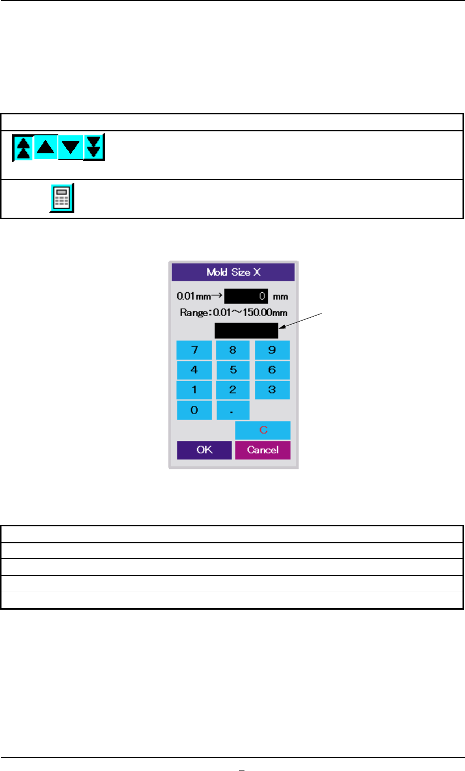
(2) Editing of Parameters
• Editing of Numerical Values
Numerical values can be changed with the increment/decrement keys
or the ten-key pad.
Table 2F18
Keys Functions
Use these keys to increment or decrement a numerical value.
The graphical representation changed according to the increment or
the decrement of the numerical value.
When pressed, this button opens the ten-key pad window.
• Parameter Entry with Ten-Key Pad
Fig. 2F104-18
Table 2F19
Keys Functions
0 to 9, ., - These keys can be used to enter numerical values.
C This key can be used to clear the current numerical value to "0"
OK This key defines the numerical value and closes the window.
Cancel This key interrupts the setting and closes the window.
When an improper parameter is specified, an error message is issued
in the message box, indicating that the entered parameter is not ac-
cepted.
In this case, press the [C] key to clear the parameter and re-enter a
correct value (a value that meets the specified range).
Message:
• Out of Range: The specified value is out of the range.
0308-004 6-144
Message Box
5.2 Library Teaching