2OM-1075-002.pdf - 第235页
AHB01ESPP 2 . 1 "Zeroing Opn." T ab The corresponding tab sheet enables the operator to zero each device (axis). • Sheet Layout When the "Zeroing Opn." tab is pressed in the "MNL OPN." windo…
AHB01ESPP
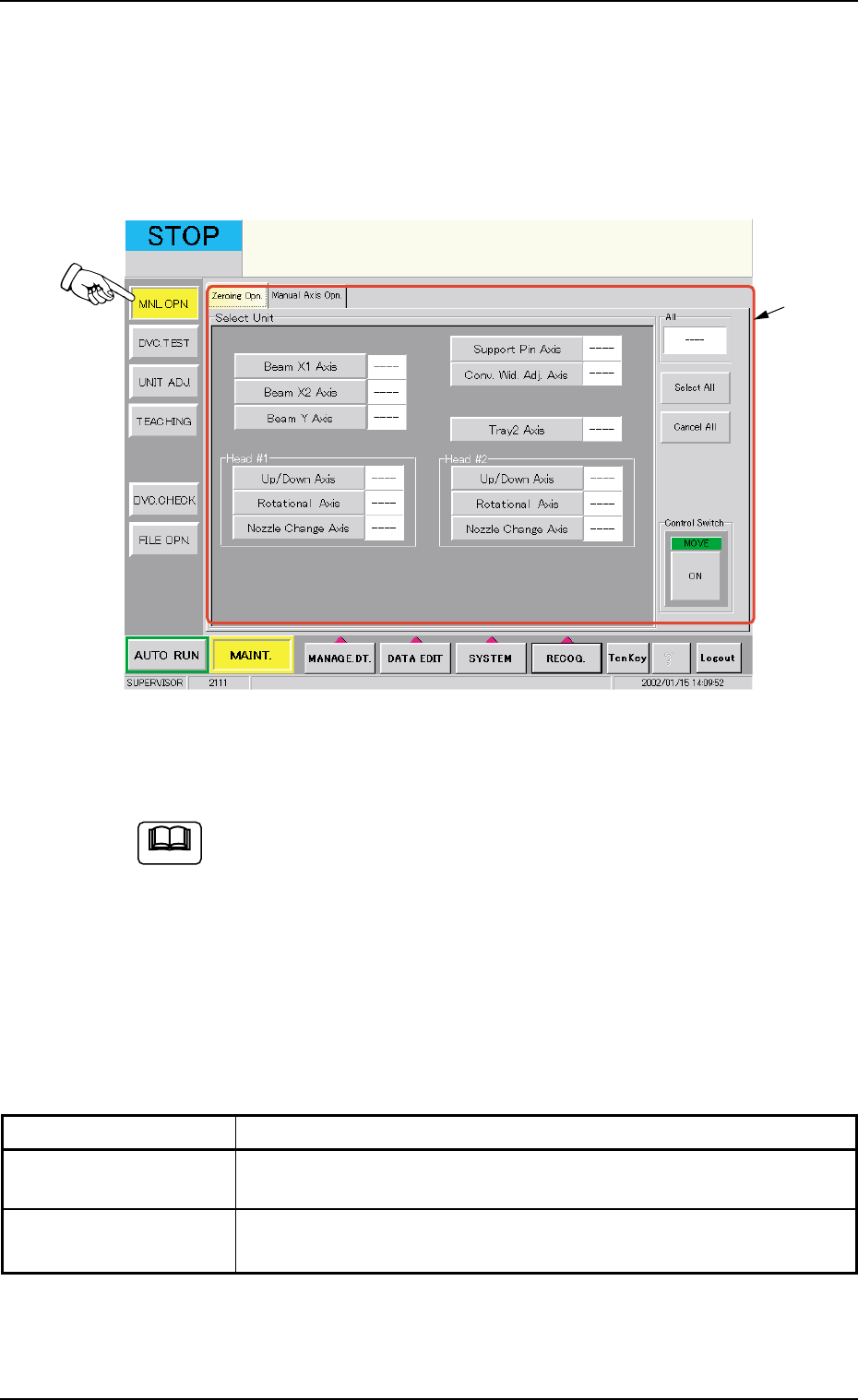
2. "MNL OPN." Window (Submenu)
• Window Layout
When the [MNL OPN.] button on the submenu bar of the "MAINT." win-
dow is pressed, the following window (submenu) opens.
Fig. 2F3 "MNL OPN." Window (Submenu)
(Provided with Multi-Layer Tray Feeder 2)
The tab sheet may look different, depending on which options
are selected.
• Window Composition
*1 Tabs and Tab Sheets
The "MNL OPN." window (submenu) is provided with the following 2
tabs. When a tab is pressed, the corresponding tab sheet appears
inside the window.
Table 2F1
Tabs Description
Zeroing Opn. The corresponding tab sheet enables the operator to zero each de-
vice.
Manual Axis Opn. The corresponding tab sheet enables the operator to perform the
manual alignment of each device.
01 12-002 6 - 5
2. "MNL OPN." Window (Submenu)
*1
Note
AHB01ESPP
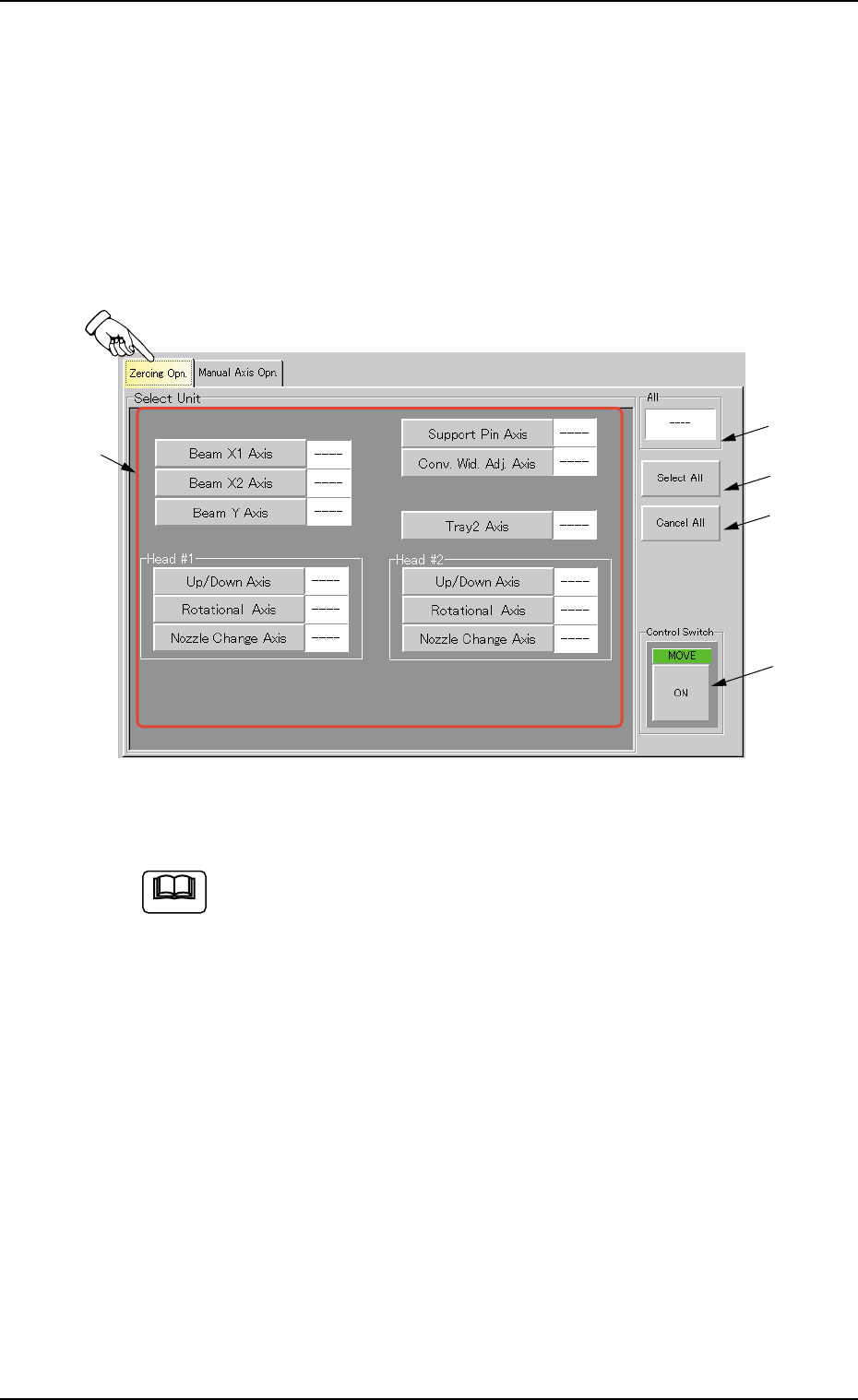
2.1 "Zeroing Opn." Tab
The corresponding tab sheet enables the operator to zero each device
(axis).
• Sheet Layout
When the "Zeroing Opn." tab is pressed in the "MNL OPN." window
(submenu), the following tab sheet opens.
Fig. 2F4 "Zeroing Opn." Tab Sheet
(Provided with Multi-Layer Tray Feeder 2)
The tab sheet may look different, depending on which options
are selected.
• Sheet Composition
*1 Select Unit Buttons
The following buttons are provided.
[Beam X1 Axis] Button
[Beam X2 Axis] Button
[Beam Y Axis] Button
[Support Pin Axis] Button
[Conv. Wid. Adj. Axis] Button
[Tray2 Axis] Button (Option)
[Up/Down Axis] Button in "Head #1" Group Box
[Rotational Axis] Button in "Head #1" Group Box
[Nozzle Change Axis] Button in "Head #1" Group Box
[Up/Down Axis] Button in "Head #2" Group Box
01 12-002 6 - 6
2.1 "Zeroing Opn." Tab
*1
*2
*3
*5
*4
Note

AHB01ESPP
[Rotational Axis] Button in "Head #2" Group Box
[Nozzle Change Axis] Button in "Head #2" Group Box
When a button is pressed, the background color turns yellow, indi-
cating that the device (axis) is selected.
Pressing the button again changes the background color to the origi-
nal one, indicating that the selection is canceled.
Each button has a box on the right side and the status of the corre-
sponding device is indicated in the box.
Refer to "Notes" in "*5".
Two or more devices can be selected.
*2 "All" Group Box
It is indicated whether or not all devices are zeroed.
"---" : All devices are not zeroed.
"Origin" : All devices are zeroed.
*3 [Select All] Button
When this button is pressed, all devices (possible to be returned to
their origins) are selected and the corresponding buttons turn yel-
low.
The [Select All] button cannot be used to select the [Sup-
port Pin Axis] and [Conv. Wid. Adj. Axis] buttons.
*4 [Cancel All] Button
When this button is pressed, the selection of all devices is can-
celed.
*5 Control Switch
When the [ENABLE] button on the operation panel is pressed in two
seconds after a device(s) is selected and the [ON] button (entitled
"MOVE") is pressed, the device is zeroed.
(a) After the zeroing operation is completed, "Origin" ap-
pears in the box on the right side of the corresponding
button.
(b) When the current position is being managed or indefi-
nite, "---" appears in the box.
Note
Note
01 12-002 6 - 7
2.1 "Zeroing Opn." Tab
Note