2OM-1075-002.pdf - 第88页
Operation Procedure (1) Press the [All Device Overall Setup] button (*1). (2) Enter the clearance data. (3) When the [ENABLE] button on the operation panel is pressed in two seconds after the [ON] button (*2) entitled &q…
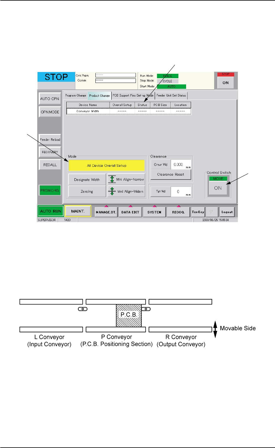
3.3 Conveyor Width Adjustment
Perform the all device overall setup operation, using the "Product
Change" tab sheet of the "PRGM CHG." window (submenu).
Fig. 2C7 "Product Change" Tab Sheet
When the all device overall setup operation is performed, the following
devices are automatically adjusted.
Width Adjustment in Conveyor Section
Fig. 2C8 Conveyor Section
3.3 Conveyor Width Adjustment
0308-004 3-10 AHB01ESPP
*2
*1
*3

Operation Procedure
(1) Press the [All Device Overall Setup] button (*1).
(2) Enter the clearance data.
(3) When the [ENABLE] button on the operation panel is pressed in two
seconds after the [ON] button (*2) entitled "MOVE" in the "Control
Switch" group box, the all device overall setup operation is started
and the result appears in the "Status" text box (*3) for each device
as follows.
"Ready" : The setup operation is completed and the devices are
located at the position "P.C.B. Width + Clearance".
"Not Ready" : The devices are located at the position "P.C.B. Width
+ Clearance" but the current position is not under
control.
"---" : The current position or program is indefinite.
"---" (red) : "Disable" is set for the setup data.
(4) Confirm that "Ready" has appeared in the "Status" text box (*3) of
each device.
When "---" has appeared in the "Status" text box (*3), perform
the manual setup operation on the conveyor width.
Refer to "7.2.2" in "Section 5 Menus for Automatic Operation"
for the manual setup operation on the conveyor width.
0107-001 3-11
AHB01ESPP
3.3 Conveyor Width Adjustment
Note
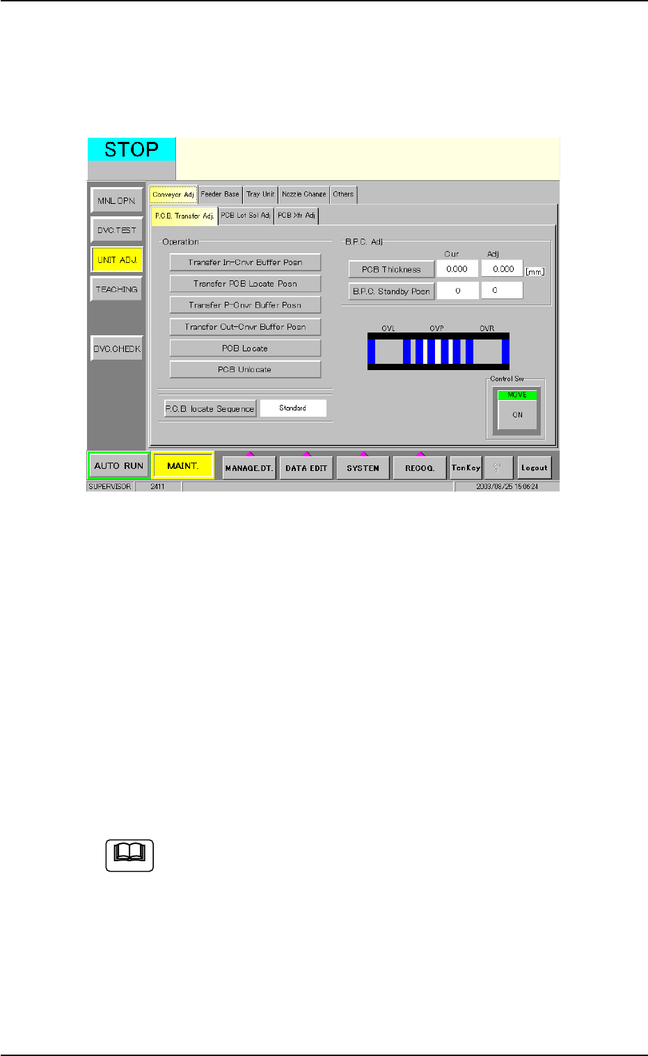
3.4 P.C.B. Positioning
The P.C.B.’s can be positioned, using the "P.C.B. Transfer Adj" tab sheet
of the "UNIT ADJ." window (submenu).
Fig. 2C9 "P.C.B. Transfer Adj" Tab Sheet
Operation Procedure
(1) Press the [PCB Thickness] button and enter a parameter as P.C.B.
thickness.
(2) Press the [B.P.C. Standby Posn] button and select a parameter as
P.C.B. standby position.
(3) Select the [Transfer PCB Locate Posn] button and press the [ON]
button (entitled "MOVE"). After that, press the [ENABLE] button on
the operation panel in two seconds.
(4) Select the [Move B.P.C. to PCB Locate Posn] button and press the
[ON] button (entitled "MOVE"). After that, press the [ENABLE] but-
ton on the operation panel in two seconds.
Refer to "4.1.1 "P.C.B. Transfer Adj" Tab" in "Section 6" for de-
tails.
3.4 P.C.B. Positioning
0308-004 3-12 AHB01ESPP
Note