2OM-1075-002.pdf - 第255页
AHB01ESPP 0206-003 6 - 2 3 3.2.2 Procedure for P .E.C. Recognition T est (1) T ransfer the P .C.B. to be tested to the P .C.B. positioning section. Confirm that each device is zeroed in the "Origin/Signal Info."…
AHB01ESPP
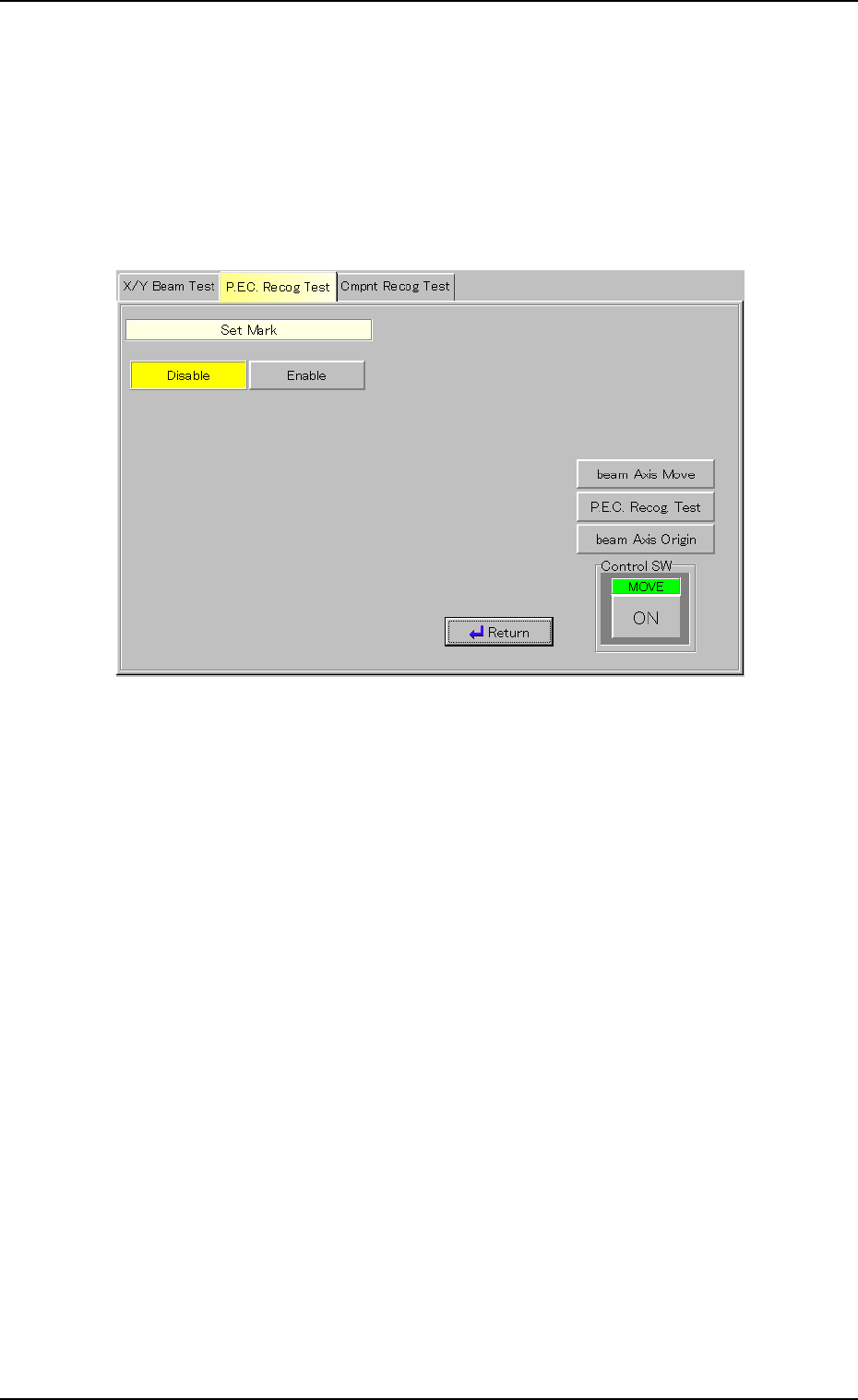
Set Mark
It can be determined whether or not the X/Y beam should be moved until
the fiducial mark comes to the center of the recognized image when the
recognition test is successful.
(1) When the [Set Mark] button is pressed in the "P.E.C. Recog Test"
tab sheet, the following window appears inside the tab sheet.
Fig. 2F16
(2) Press the [Disable] or the [Enable] button.
The background color of the button turns yellow, indicating that the
corresponding mark positioning function is selected.
(3) When the [Return] button is pressed, the "P.E.C. Recog Test" tab
sheet appears.
Gain
(1) Follow the same procedure as "Mark Size D1" to enter a parameter
in the text box.
Level
(1) Follow the same procedure as "Mark Size D1" to enter a parameter
in the text box.
0206-003 6-22
3.2 "P.E.C. Recog Test" Tab
AHB01ESPP
0206-003 6-23
3.2.2 Procedure for P.E.C. Recognition Test
(1) Transfer the P.C.B. to be tested to the P.C.B. positioning section.
Confirm that each device is zeroed in the "Origin/Signal Info." tab
sheet. (Operation Sequence: [AUTO RUN] Button Æ [AUTO OPN.]
Button Æ "AUTO OPN." Window (Submenu)" Æ "Origin/Signal Info."
Tab Sheet)
(2) Set various parameters for the P.C.B. recognition test.
Refer to "3.1.1 Various Data Settings for P.C.B. Recognition Marks"
for details.
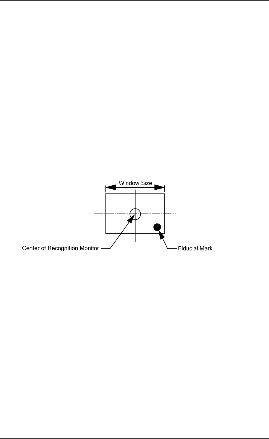
(3) Specify the position of the X/Y beam to be shifted to with the [beam
Axis Move] button such that the fiducial mark (used for a recognition
test) enters the window size (visual field of camera).
It is recommended that the fiducial mark should be located close to
a corner of the window size.
Fig. 2F17 Recognition Test Position
3.2 "P.E.C. Recog Test" Tab
AHB01ESPP
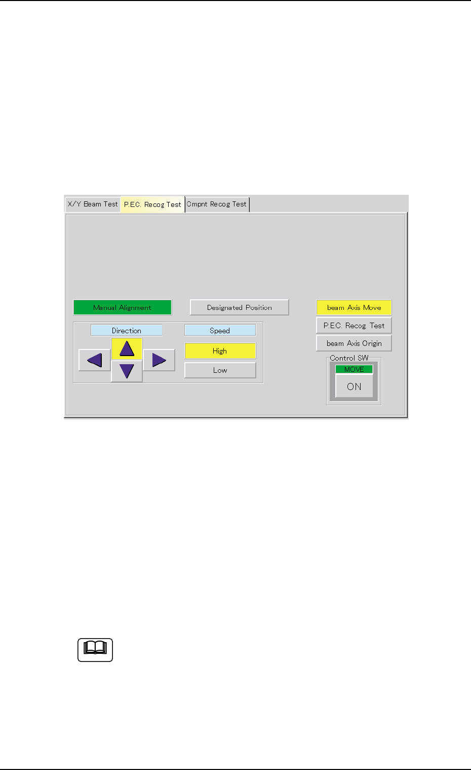
There are two X/Y beam movement functions - "Manual Alignment" and
"Designated Position". When "Manual Alignment" is selected, it is pos-
sible to move the X/Y beam through manual alignment operation while
observing the recognized image. "Designated Position" makes it pos-
sible to move the X/Y beam to the designated position by using numeri-
cal values.
• Manual Alignment
(1) When the [beam Axis Move] button is pressed, the following sheet
appears.
Fig. 2F18
(2) Press the [High] or the [Low] button to specify the speed of the X/Y
beam movement.
The direction of the X/Y beam movement must also be specified by
pressing one of the "Direction" buttons (Up, Right, Down, and Left
Arrows).
(3) Press the [ENABLE] button on the operation panel in two seconds
after the [ON] button (entitled "MOVE") to move the X/Y beam to the
recognition test position (Fig. 2F18).
When the [ENABLE] button on the operation panel is pressed in
2 seconds after the manual alignment operation is performed
and the [P.E.C. Recog. Test] and [ON] (entitled "MOVE") but-
tons are pressed, a P.E.C. recognition test is made and the
"P.E.C. Recog Test" tab sheet resumes.
0308-004 6-24
Note
3.2 "P.E.C. Recog Test" Tab