2OM-1075-002.pdf - 第167页
AHB01ESPP *3 [ ] and [ ] Buttons Select the component for which the component carriage data should be changed. When the registered components occupy more than 1 page, use the scroll bar (up and down arrows) on the right …
AHB01ESPP
Table 2E4
Tabs Description
Feeder #1 The corresponding tab sheet enables the operator to change the
component carriage data for the components allocated on Feeder
Base #1.
Feeder #3 The corresponding tab sheet enables the operator to change the
component carriage data for the components allocated on Feeder
Base #3.
Feeder #4 The corresponding tab sheet enables the operator to change the
component carriage data for the components allocated on Feeder
Base #4.
TRAY2[R] F701-F799 This is an optional function.
Refer to the instruction manual of the multi-layer tray feeders for
details.
TRAY2[R] F801-F899 This is an optional function.
Refer to the instruction manual of the multi-layer tray feeders for
details.
Vib. Stick A F341-F349 The corresponding tab sheet enables the operator to change the
component carriage data for the components allocated on FB #4
VIB Feeder #3.
Vib. Stick A F361-F369 The corresponding tab sheet enables the operator to change the
component carriage data for the components allocated on FB #3
VIB Feeder #1.
*2 [Screens 1/4] Button
When this button is pressed, different titles appear in each tab sheet.
See Figs. 2E21 to 2E23.
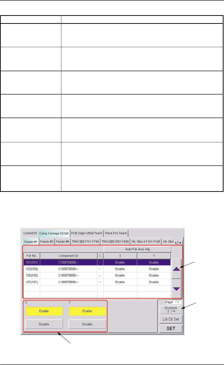
Fig. 2E21 "Comp Carriage Dt Edit" Tab Sheet (2/4)
5.2 "Comp Carriage Dt Edit" Tab
0308-003 5-25-6
*2
*3
*6
AHB01ESPP
*3 [ ] and [ ] Buttons
Select the component for which the component carriage data should
be changed.
When the registered components occupy more than 1 page, use
the scroll bar (up and down arrows) on the right edge of the tab
sheet to scroll up or down the list of components.
The "Direction (*4)", "Type (*5)", "X (*6)", "Y (*6)", "Selected Nozzle
#1 (*7)", "Selected Nozzle #2 (*7)", "Pickup Level (*8)", and "Place-
ment Level (*9)" group boxes appear at the lower area of the tab
sheet according to the listed items.
*4 "Direction" Group Box
Select one of the [+0 deg], [+90 deg], [+180 deg], and [+270 deg]
buttons as a direction.
*5 "Type" Group Box
Select one of the [Paper], [Embossed], and [Adhesive] buttons as a
component packaging type.
To change the selection in the "X", the "Y", the "Selected
Nozzle #1", "Selected Nozzle #2", the "Pickup Level" or the
"Placement Level" group box, press the [Screens #/4] (*2)
to open the subsequent pages.
*6 "X" and "Y" Group Boxes
Select the [Enable] or the [Disable] button to determine whether the
pickup position correction function should be used or not.
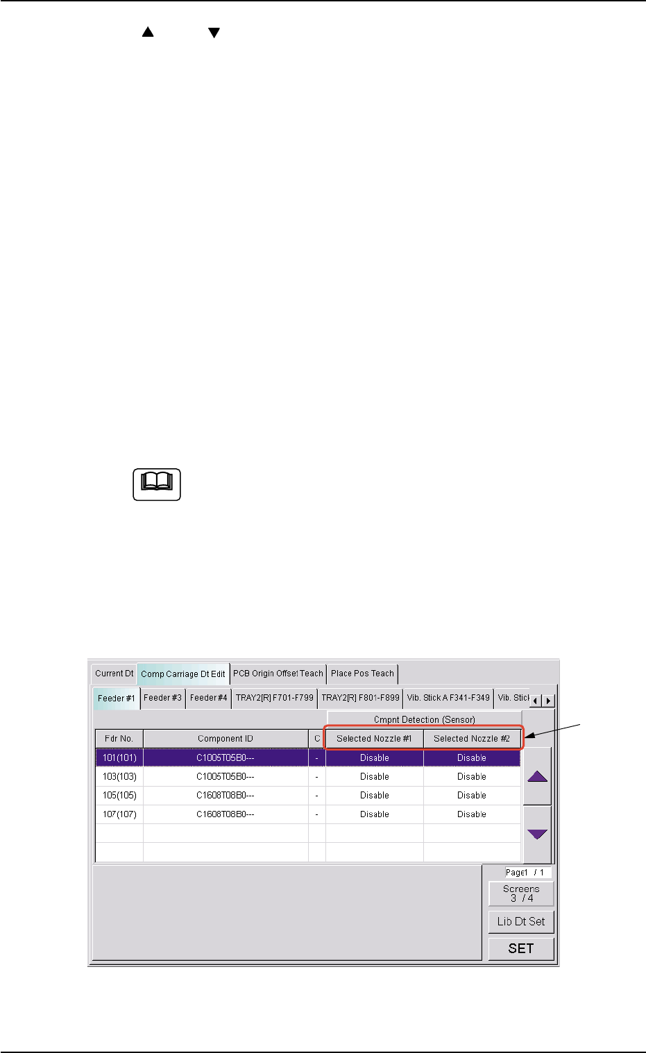
Fig. 2E22 "Comp Carriage Dt Edit" Tab Sheet (3/4)
5.2 "Comp Carriage Dt Edit" Tab
0308-003 5-25-7
*7
Note
AHB01ESPP
*7 "Selected Nozzle #1 and #2" Group Box
Select the [Disable] or the [Enable] button to determine whether the
component detection function should be used or not.
When one of the following requirements is met, the component
detection becomes unavailable.
Table 2E5
Item Requirements Remarks
Nozzle ID EC** Mechanical Chuck Nozzle
EE** Mechanical Chuck Nozzle
Pickup Hole Areas Less than 0.7854 mm
2
Total of Pickup Hole Areas
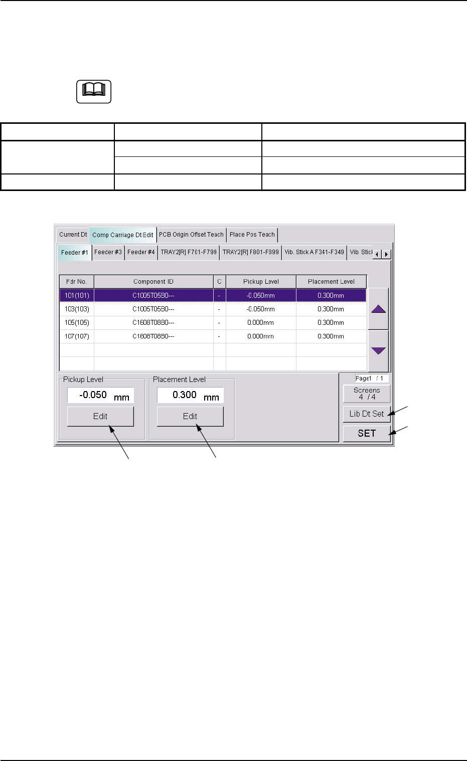
Fig. 2E23 "Comp Carriage Dt Edit" Tab Sheet (4/4)
*8 "Pickup Level" Group Box
The current pickup level is indicated in the text box.
To change the pickup level, press the [Edit] button. A "TenKey" edit
window opens. Enter the desired level with the ten-key pad and press
the [Set] button.
*9 "Placement Level" Group Box
The current placement level is indicated in the text box.
To change the placement level, press the [Edit] button. A "TenKey"
edit window opens. Enter the desired level with the ten-key pad and
press the [Set] button.
0308-003 5-25-8
5.2 "Comp Carriage Dt Edit" Tab
*8
*9
*10
*11
Note