2OM-1075-002.pdf - 第85页
3.2.3 Setting of P .C.B. Support Pins and Precautionary Items on Detachment Fig. 2C4 P .C.B. Support Pin Fig. 2C5 Unavailable Position of Pin Insertion Be sure to remove the P .C.B. support pin before the automatic set-u…
3.2.2 Setting of P.C.B. Support Pins with Power "OFF"
The load power to the motors, etc., is shut off but the
setting operation must be performed carefully, protect-
ing your hands from moving mechanisms.
Operation Procedure
(1) Check the condition of the P.C.B.’s to be handled.
(Check the size and thickness of the P.C.B.’s and whether or not
components are previously placed on the back.)
(2) Determine whether or not the set-up operation must be performed.
• When the set-up operation is not required (the same condition as
that of the current production can be applied), perform the pro-
gram change operation for the automatic operation.
• When the set-up operation is required (different condition from
that of the current production), proceed to Step (3).
(3) Stop the operation and set the power breaker crank to "OFF".
To prevent the power breaker crank from being set to
"ON" by mistake, lock the crank using a padlock kept
by the person in charge.
(4) Open the front safety door and detach all feeders.
(5) Move the X/Y beam to the rear side.
(6) Remove the P.C.B. support pins.
Otherwise, the movable chute will collide with the P.C.B. support
pins when the set-up operation is performed.
Refer to "3.2.3 Setting of P.C.B. Support Pins and Precautionary
Items on Detachment" for details.
(7) Check that a P.C.B. support pins, etc., is not left behind on the backup
table.
Check that no component or dust, etc., has fallen into the holes on
the backup table.
(8) Close the front safety door and set the power breaker to "ON".
(9) After zeroing, set up the conveyor width.
Refer to "7.2 "Product Change" Tab" in "Section 5" for details.
(10) Follow the procedure similar to Step (3) and turn off the power.
(11) Open the front safety door and push the X/Y beam back to the rear
side.
(12) Insert the P.C.B. support pins vertically into the holes on the backup
table.
Be sure to insert the pins such that they are dispersed equally over
the whole area of the P.C.B. to be used
0308-002 3-7
AHB01ESPP
3.2 Setting of P.C.B. Support Pins
CAUTION
CAUTION
Note
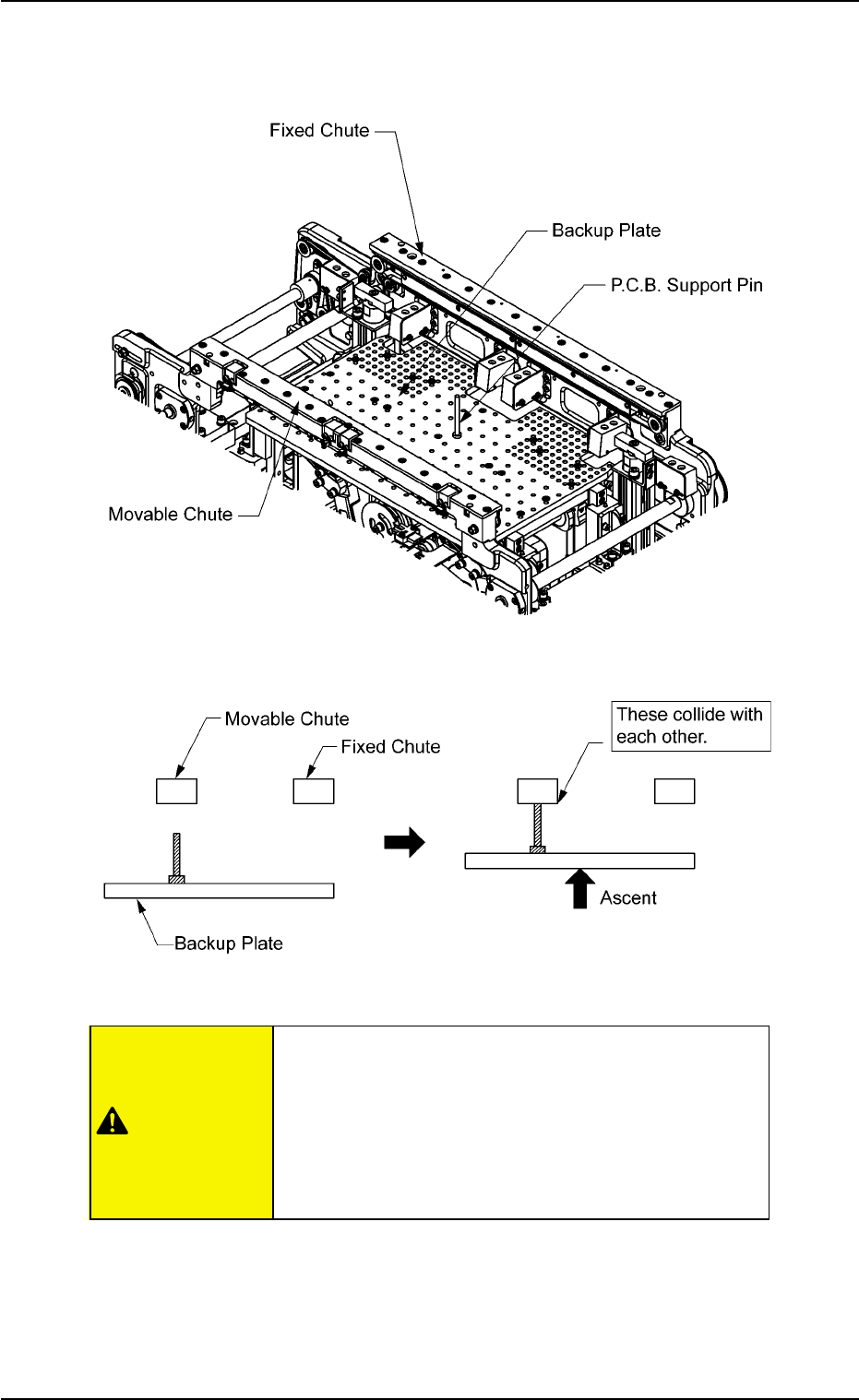
3.2.3 Setting of P.C.B. Support Pins and Precautionary Items on
Detachment
Fig. 2C4 P.C.B. Support Pin
Fig. 2C5 Unavailable Position of Pin Insertion
Be sure to remove the P.C.B. support pin before the
automatic set-up operation.
When a P.C.B. support pin is inserted at the bottom
side of the movable chute as shown in Fig. 2C5, it
may collide with the backup plate while the plate is
moving up.
0308-004 3-8 AHB01ESPP
3.2 Setting of P.C.B. Support Pins
CAUTION
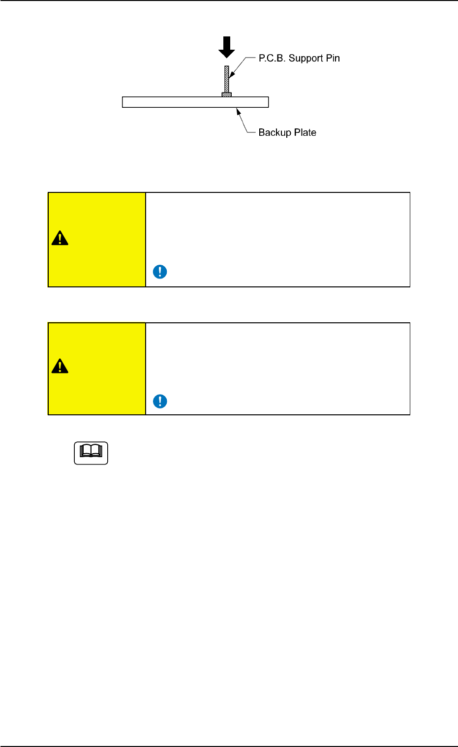
Fig. 2C6 Setting of P.C.B. Support Pins
Be sure to insert the P.C.B. support pins at right
angles.
If the pins are inserted improperly, the machine
will break down.
When some components are previously placed
on the back of the P.C.B. and P.C.B. support pins
are inserted, make sure that no pin touches a com-
ponent.
When a component is trapped or dust has accumulated on
the backup plate, the height of the P.C.B. support pins can-
not be set correctly.
In this case, remove the component or dust with a vacuum
cleaner, etc. (Air Blowing Prohibited)
0308-003 3-9 AHB01ESPP
3.2 Setting of P.C.B. Support Pins
CAUTION
CAUTION
Note