2OM-1075-002.pdf - 第153页
AHB01ESPP 3 . 4 "T est Run" T ab The corresponding tab sheet enables the operator to specify a test op- eration. • Sheet Layout When the "T est Run" tab is pressed in the "OPN. MODE" window …
AHB01ESPP
Pickup Level for TIM-5000 Series
Because the distance between the reference level of the em-
bossing and the pickup surface must be entered, it is required
to make the manual calculation (Principal Pickup Level + Com-
ponent Thickness (T) - Component Thickness (t)) and enter
the result of the calculation as a pickup level.
Pickup Level for TIM-X100
The distance between the reference level of embossing and
the uppermost surface of the component must be entered.
The component pickup surface (Principal Pickup Level + Com-
ponent Thickness (T) - Component Thickness (t)) is automati-
cally calculated.
*10 "Short Nozzle Mode" Group Box
"Disable" or "Enable" can be selected to determine whether or not
the short nozzles should be handled.
[Disable] Button: Only the standard nozzles can be used.
[Enable] Burron: The short nozzles can be used.
Table 2E2-1
Nozzle Types Standard Short 1 Short 2
Nozzle Length: L 19.0 13.0 11.0
Applicable Thickness 0 to 5.0 5.0 to 11.0 7.0 to 13.0
of Component
Nozzle ID E*** D*** C***
(Example: EA06) (Example: DA06) (Example: CA06)
*11 [Prev] Button
When pressed, this button opens the first page.
3.3 "OPN. Mode" Tab
0308-001 5-22-2
AHB01ESPP
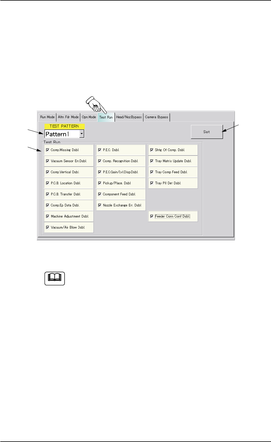
3.4 "Test Run" Tab
The corresponding tab sheet enables the operator to specify a test op-
eration.
• Sheet Layout
When the "Test Run" tab is pressed in the "OPN. MODE" window
(submenu), the following tab sheet appears inside the window.
Fig. 2E14 "Test Run" Tab Sheet (Provided with Multi-Layer Tray Feeder 2)
The tab sheet may look different, depending on which options
are selected.
• Sheet Composition
*1 TEST PATTERN
When the drop-down arrow (located at the right side of the drop-
down list box) is pressed, the drop-down list opens. Select the pat-
tern to be set as a test run.
*2 Test Run
Make a combination of the following functions as a test mode.
The following buttons are provided.
[Comp. Missing Dsbl.] Button
[Vacuum Sensor Err. Dsbl.] Button
[Comp. Vertical Dsbl.] Button
[P.C.B. Location Dsbl.] Button
3.4 "Test Run" Tab
*1
*2
*3
0308-004 5-23
Note

AHB01ESPP
[P.C.B. Transfer Dsbl.] Button
[Comp. Ep Data Dsbl.] Button
[Machine Adjustment Dsbl.] Button
[Vacuum/Air Blow Dsbl.] Button
[P.E.C. Dsbl.] Button
[Comp. Recognition Dsbl.] Button
[P.E.C. Gain/Lvl. Disp. Dsbl.] Button
[Pickup/Place. Dsbl.] Button
[Component Feed Dsbl.] Button
[Nozzle Exchange Err. Dsbl.] Button
[Shtg. Of Comp. Dsbl.] Button
[Tray Matrix Update Dsbl.] Button (Option)
[Tray Comp Feed Dsbl.] Button (Option)
[Tray Pll Det Dsbl.] Button (Option)
[Feeder Conn Conf Dsbl.] Button
When one of the above buttons is pressed, a check mark appears
in the check box of the button and the background color of the but-
ton turns creamy white, indicating that the function is selected.
To cancel the selection, press the button again. The check mark in
the check box disappears and the background color of the button
turns gray (original color).
Several functions can be selected.
*3 [Set] Button
The selected functions are set as the selected test pattern.
0308-004 5-24
3.4 "Test Run" Tab
Note