2OM-1075-002.pdf - 第144页
AHB01ESPP [Priority Of Comp.] Button When a component shortage error is detected, the machine does not stop immediately . Although a message is issued as machine information to prompt the operator to replenish components…
AHB01ESPP
3.3 "Opn. Mode" Tab
The corresponding tab sheet enables the operator to specify various
operation modes such as "Recovery Mode", "Auto. Fdr. Axis Set", "PCB
Counter Stop Mode", etc.
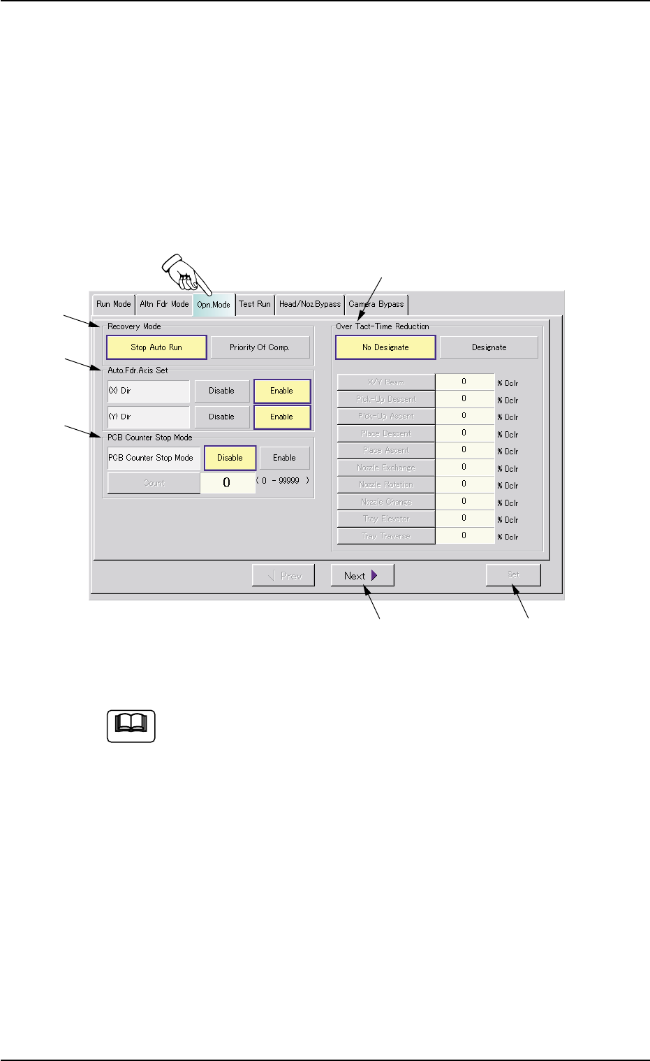
• Sheet Layout
When the "Opn. Mode" tab is pressed in the "OPN. MODE" window
(submenu), the following tab sheet appears inside the window.
Fig. 2E12 "Opn. Mode" Tab Sheet (Provided with Multi-Layer Tray Feeder 2)
The tab sheet may look different, depending on which options
are selected.
• Sheet Composition
*1 Recovery Mode
It can be determined in which mode "Stop Auto Run" or "Priority Of
Comp." the machine should be set when a component shortage
error is detected.
[Stop Auto Run] Button
When a component shortage error is detected, the machine stops
running immediately.
3.3 "Opn. Mode" Tab
0206-003 5-15
*5
*3
*2
*1
*4
*6
Note

AHB01ESPP
[Priority Of Comp.] Button
When a component shortage error is detected, the machine does
not stop immediately.
Although a message is issued as machine information to prompt
the operator to replenish components, the machine keeps on plac-
ing the other components.
The machine places all remaining components on a P.C.B. and stops
running without discharging the P.C.B.
Relation between Recovery Mode and Alternate Function
(1) "Priority Of Comp." Selected
• The alternate function is not activated immediately for the
pertinent placement step (step for which the recovery
function should be implemented) after a pick-up or a com-
ponent shortage error, etc., is detected.
• The alternate function is activated after the machine has
placed the component in the last step specified in the
pattern program data.
(2) "Priority Of Comp." Not Selected
The alternate function is activated immediately after a com-
ponent shortage error (including the process specified in
"Error process 1" and "Error process 2" in the component
library data) is detected.
0206-003 5-16
3.3 "Opn. Mode" Tab
Note

AHB01ESPP
*2 Auto. Fdr. Axis Set
This function is used to correct the feeder offset data through statis-
tical processing of the difference between the nozzle and compo-
nent center positions calculated during component recognition ac-
cording to the parameters specified as "Auto feeder axis adjust-
ment set" in the "Auto Operation Setup" tab sheet in the "Machine
System Data" window.
"Enable" or "Disable" can be selected to determine whether or not
the "Auto. Fdr. Axis Set" function should be used.
Each parameter ("Enable" or "Disable" for "Auto. Fdr. Axis Set" func-
tion) can be set separately for X and Y directions.
(1) (X) Dir
[Disable] Button
When this button is pressed, the automatic feeder axis set-
ting function is not used for "X Dir".
[Enable] Button
When this button is pressed, the automatic feeder axis set-
ting function is used for "X Dir".
(2) (Y) Dir
[Disable] Button
When this button is pressed, the automatic feeder axis set-
ting function is not used for "Y Dir".
[Enable] Button
When this button is pressed, the automatic feeder axis set-
ting function is used for "Y Dir".
(a) In normal cases, press the [Enable] button.
(b) The "Auto Operation Setup" tab sheet can be opened
through the operation sequence - "[SYSTEM] Button on
Main Menu Bar Æ "SYSTEM SEL." Menu Æ [SYS DATA]
Button Æ "Machine System Data" Window Æ "Auto Op-
eration Setup" Tab Sheet".
(c) The designation of the automatic feeder axis setting func-
tion for a specific feeder can be canceled in the compo-
nent library data.
(d) When the machine is set in the "RUN" or the "WAIT" mode,
the data save operation (saving of changed settings) can-
not be performed.
0206-003 5-17
3.3 "Opn. Mode" Tab
Note