2OM-1075-002.pdf - 第307页
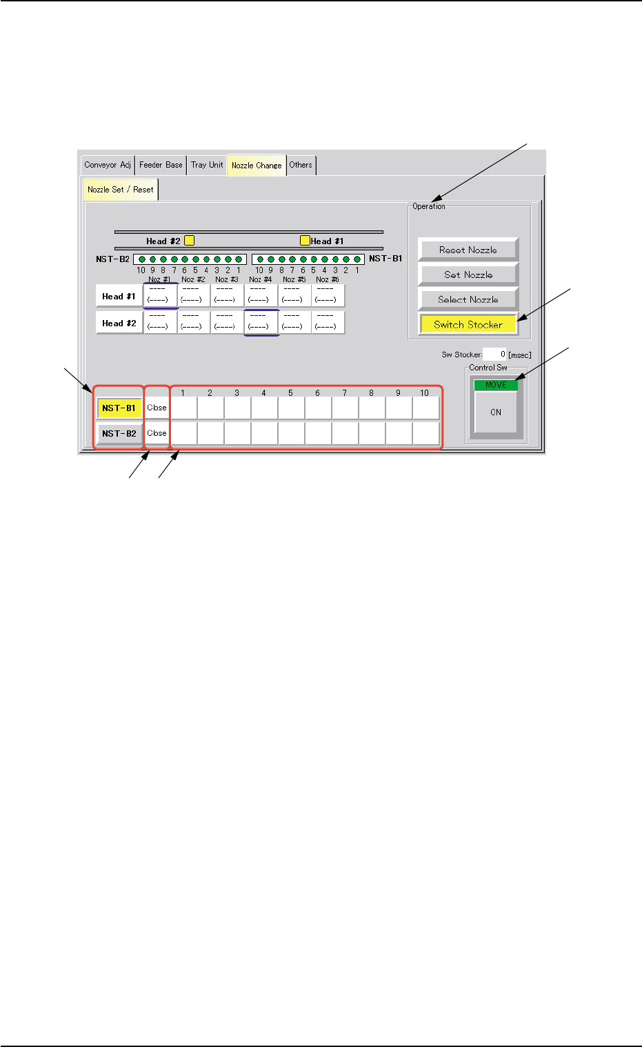
AHB01ESPP • Procedure for Nozzle Stocker Opening/Closing Operation (1) Press the [Switch Stocker] button (*4). When pressed, the background color of this button turns yellow , indicating that the nozzle stocker selection…
AHB01ESPP
• Do not select any nozzle when a component is
picked up by the head.
Otherwise, the vacuum will be turned off, releas-
ing the component from the head.
4.3 "Nozzle Change" Tab
*10
*3
*6
0308-003 6-74
CAUTION
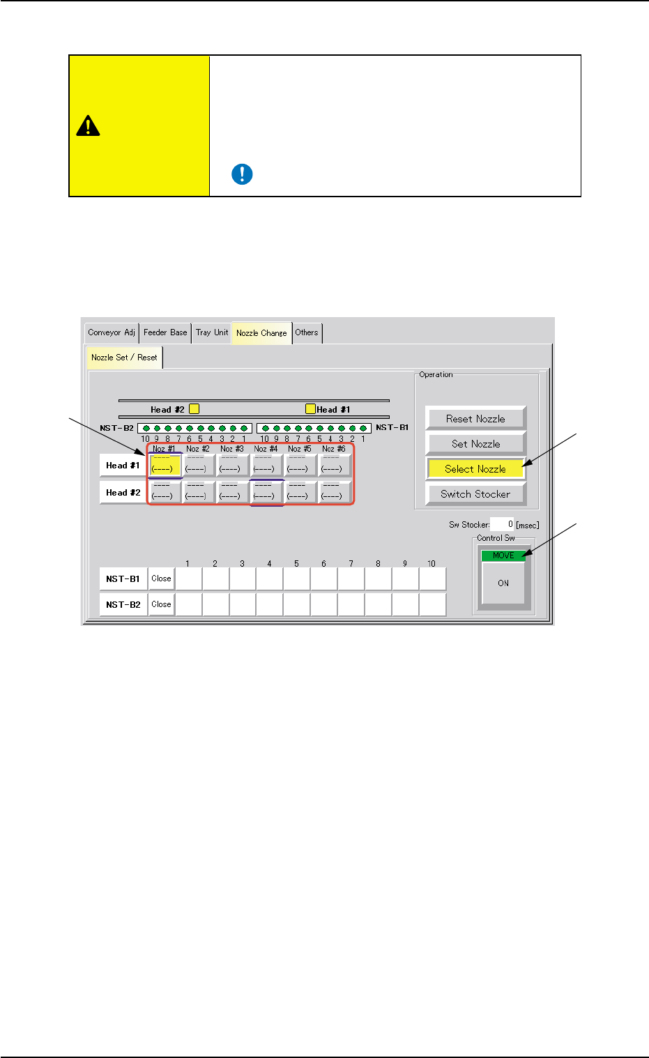
• Procedure for Nozzle Selection
(1) Press the [Select Nozzle] button (*3).
The background color of the button turns yellow, indicating that the
nozzle selection (head) buttons (*6) are set active.
Fig. 2F54 “Nozzle Change” Tab Sheet
([Select Nozzle] Button Selected)
(2) Select the nozzle to be moved to the nozzle #1 position (nozzle
change position).
The background color of the selected button turns yellow.
(3) Press the [ENABLE] button on the operation panel in 2 seconds
after the [ON] button (*10 entitled “MOVE”).
The selected nozzle moves to the nozzle #1 position.
AHB01ESPP
• Procedure for Nozzle Stocker Opening/Closing Operation
(1) Press the [Switch Stocker] button (*4).
When pressed, the background color of this button turns yellow,
indicating that the nozzle stocker selection button (*7) is set active.
Fig. 2F55 "Nozzle Change" Tab Sheet ([Switch Stocker] Button Selected)
(2) Press one of the nozzle stocker selection buttons (*7) ([NST-B1] or
[NST-B2] button) to select the nozzle stocker to be opened or closed.
The background color of the selected button turns yellow.
(3) When the [ENABLE] button on the operation panel is pressed in 2
seconds after the [ON] button (entitled "MOVE") (*10), the opening
or closing action of the specified nozzle stocker takes place.
(4) It is indicated if the nozzle stocker is opened or closed in the nozzle
stocker open/closed status field (*8).
"Open" or "Close" appears.
0308-004 6-75
4.3 "Nozzle Change" Tab
*1
*10
*7
*9*8
*4
AHB01ESPP
0308-004 6-76
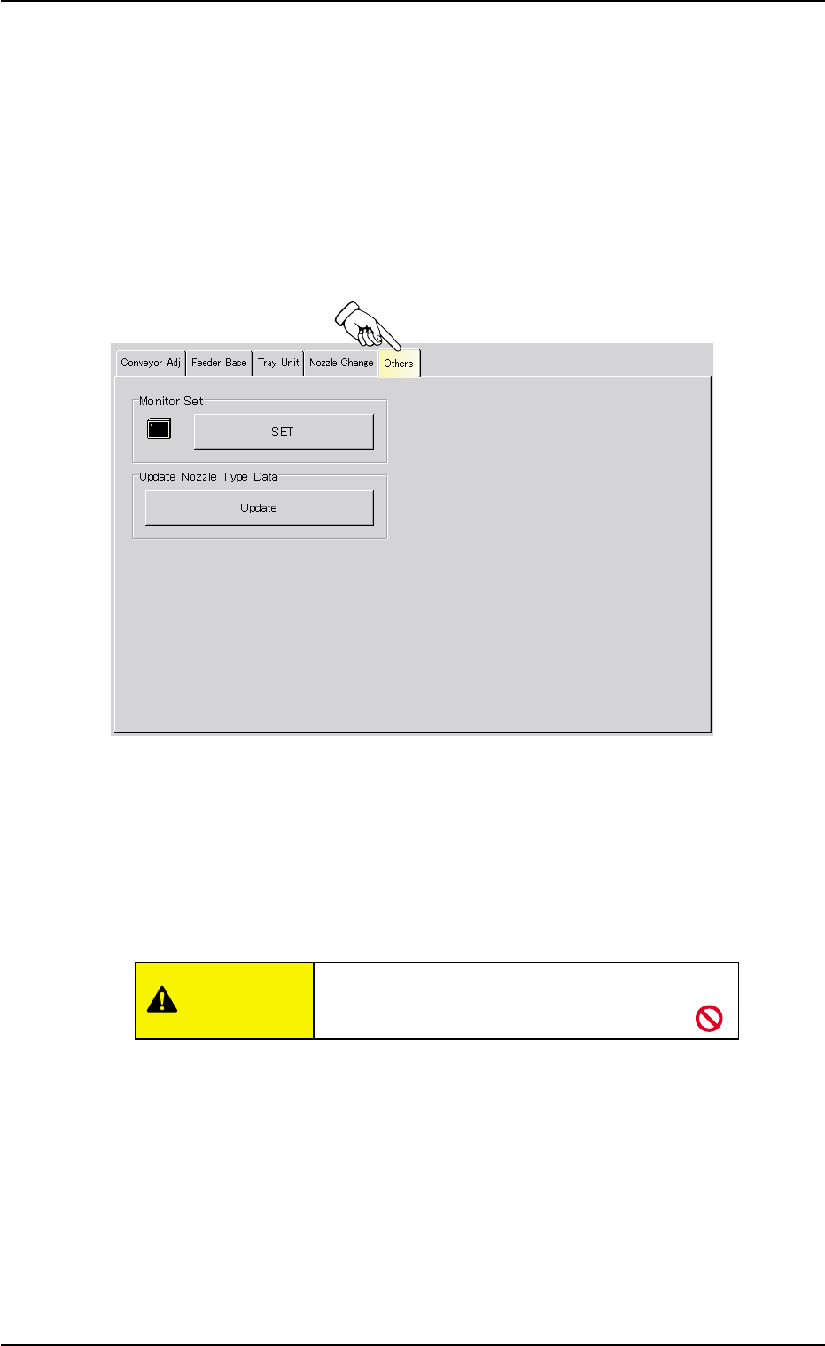
4.4 "Others" Tab
4.4 "Others" Tab
The corresponding tab sheet enables the operator to adjust the other
devices. The tab sheet makes it possible to adjust the touch screen and
update the nozzle type data.
• Sheet Layout
When the "Conveyor Adj" tab is pressed in the "UNIT ADJ." window
(submenu), the following tab sheet appears.
Fig. 2F55-1 "Others" Tab Sheet
• Sheet Composition
*1 "Monitor Set" Group Box
The touch screen can be adjusted.
When the [SET] button is pressed, the window for adjustment opens.
Do not press any buttons other than [Calibra-
tion] and [Exit] buttons.
• Adjustment Procedure
(1) Press the [Calibration] button.
(2) Press the marked area on the screen.
(3) After the adjustment, press the [Exit] button. The window for
adjustment closes.
*2 "Update Nozzle Type Data" Group Box
The nozzle type data registered as standard one is loaded onto the
machine.
CAUTION