2OM-1075-002.pdf - 第332页
AHB01ESPP *2 "Fdr . No." Group Box Set the feeder No. to be taught. When the [Fdr . No.] button is pressed, the "Feeder No. Set" sheet appears. Refer to "5.1.4 "Feeder No. Set" Sheet&qu…
AHB01ESPP
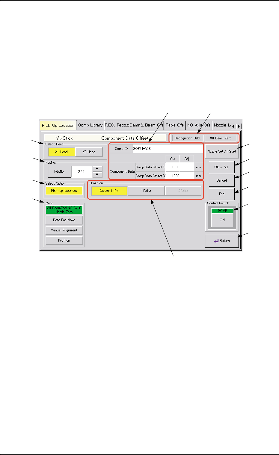
5.1.3 "Vib. Stick Component Data Offset" Sheet
The corresponding sheet makes it possible to perform a teaching op-
eration to align the center of the vacuum nozzle with the center of the
component supplied from the vibratory stick feeder.
••
••
• Sheet Layout
When the [Vib. Stick Component Data Offset] button is pressed in the
"Pick-Up Location" tab sheet, the following sheet appears.
Fig. 2F71 "Vib. Stick Component Data Offset" Sheet
••
••
• Sheet Composition
*1 "Select Head" Group Box
Select the head to be used for teaching operations.
The following buttons are provided in this group box.
[X1 Head] Button
When this button is pressed, a teaching operation is performed,
using the X1 head.
[X2 Head] Button
When this button is pressed, a teaching operation is performed,
using the X2 head.
5.1 "Pick-Up Location" Tab
0206-003 6-99
*1
*2
*3
*4
*8
*9
*10
*11
*12
*5
*13
*7
*6

AHB01ESPP
*2 "Fdr. No." Group Box
Set the feeder No. to be taught.
When the [Fdr. No.] button is pressed, the "Feeder No. Set" sheet
appears.
Refer to "5.1.4 "Feeder No. Set" Sheet" for details.
*3 "Select Option" Group Box
[Pick-Up Location] Button
When this button is pressed, the positional offset data can be taught.
*4 "Mode" Group Box
Various actions can be selected.
The following buttons are provided in this group box.
[All Beam (Incl. NC Axis) Heads Zero] Button
When this button is pressed, all X/Y beams are zeroed.
When the [ENABLE] button on the operation panel is pressed in 2
seconds after this button and the [ON] button (entitled "MOVE"), the
zeroing operation starts.
[Data Pos. Move] Button
When pressed, this button moves the P.E.C. recognition camera to
the position where the positional offset data in the placement feeder
location data is referred to.
When the [ENABLE] button on the operation panel is pressed in 2
seconds after this button and the [ON] button (entitled "MOVE"), the
P.E.C. recognition camera starts moving.
[Manual Alignment] Button
When pressed, this button makes it possible to move the P.E.C.
recognition camera, using the pointing device.
Press this button and select one of the buttons in the "Position"
group box (*5) for the operation.
5.1 "Pick-Up Location" Tab
0206-003 6-100
AHB01ESPP
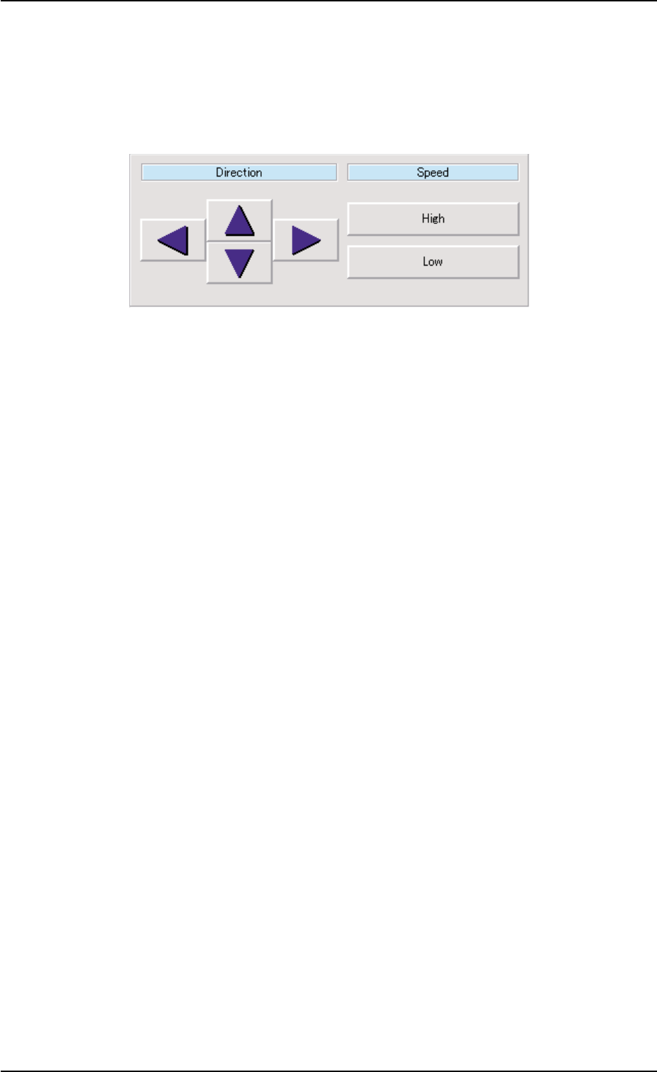
[Position] Button
The P.E.C. recognition camera can be moved through the manual
alignment operation after the direction and speed are specified.
When this button is pressed, a dialog box opens. It is provided with
the "Direction" and "Speed" buttons.
Fig. 2F72
When the [ENABLE] button on the operation panel is pressed in 2
seconds after selection of the direction and speed and the [ON]
button (entitled "MOVE"), the P.E.C. recognition camera keeps on
moving as long as the [ENABLE] button is held down.
*5 "Position" Group Box
The following buttons are provided in this group box.
[Center 1-Pt.] Button
When the [ENABLE] button on the operation panel is pressed in 2
seconds after this button and the [ON] button (entitled "MOVE"), the
P.E.C. recognition camera moves to the component center position
(Design Position + Feeder (A) Offset + Feeder (B) Offset) of the
related feeder and captures an image.
Proceed to the operation of the pointing device and execute the
manual alignment operation.
[1Point] and [2Point] Buttons
These buttons are used to align the component with 2 diagonally-
located points.
Use these buttons when the maximum outside dimensions of the
component is "10 × 10 mm" or more (when the screen cannot cover
the whole image of the component).
5.1 "Pick-Up Location" Tab
0206-003 6-101