2OM-1075-002.pdf - 第360页
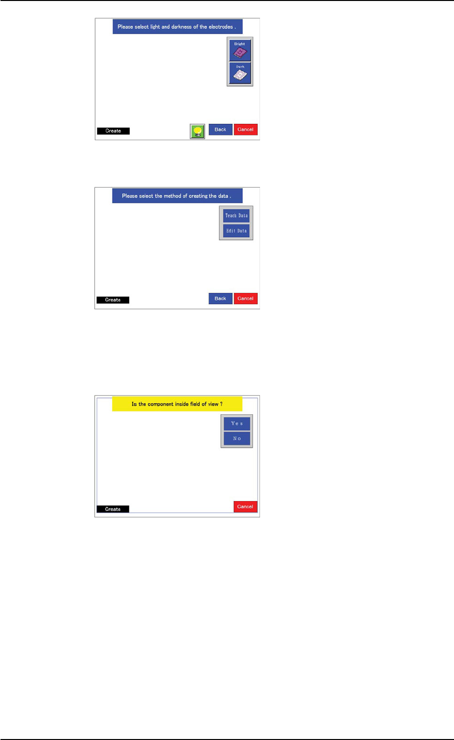
AHB01ESPP (9) Specify the rough size and location of the component such that the whole image of the component can stay inside the yellow frame. Use an adjuster for the po- sitional adjustment. Refer to "5.2.10"…
AHB01ESPP
(6) Select the brightness of the
electrodes, compared with
the mold.
Select "Bright" in normal
cases.
When the molded area looks
almost white, select "Dark".
The window in Step (7)
opens.
(7) Specify how to create data.
When the [Teach Data] but-
ton is selected, the window
in Step (8) opens.
When the [Edit Data] button
is selected and the large
view function is used, the
window in Step (8) opens.
When a function other than
the large view one is used,
the window in Step (16)
opens.
(8) Confirm that the image of
the component is inside the
view.
When part of the image is
out of the view, press the
[No] button.
The divided images are cap-
tured.
When a function other than
the large view one is used,
this window does not open.
In this case, the window in
Step (12) opens.
Confirm that the whole image of the component is inside the light
blue frame.
When the [Yes] button is selected, the window in Step (10) opens.
When the [No] button is selected, the divided images are captured
and the window in Step (9) opens.
5.2 Library Teaching
0308-004 6-127
Fig. 2F94
Fig. 2F95
Fig. 2F96
AHB01ESPP
(9) Specify the rough size and
location of the component
such that the whole image
of the component can stay
inside the yellow frame.
Use an adjuster for the po-
sitional adjustment. Refer to
"5.2.10" for the detailed infor-
mation on the adjuster.
When the yellow frame must
be adjusted, leave slight
margins beside the frame
(the frame not in close prox-
imity to the outline of the
component).
When the [Teach Data] button is selected in Step (7), the window in
Step (10) opens.
When the [Edit Data] button is selected in Step (7), the window in
Step (16) opens.
(10) A window opens and shows
an image of the component
to determine if the image is
inside the transmission dif-
fusion plate or not for the
confirmation of whether or
not the transmitted image
can be captured.
When a function other than
the large view one is used,
this window does not open.
Instead, the window in Step (12) opens.
Confirm that the whole image of the component is inside the light
blue frame.
When the [Yes] button is selected, the window in Step (12) opens.
When the [No] button is selected, the window in Step (11) opens.
5.2 Library Teaching
0308-004 6-128
Fig. 2F97
Fig. 2F98
AHB01ESPP
0308-004 6-129
5.2 Library Teaching
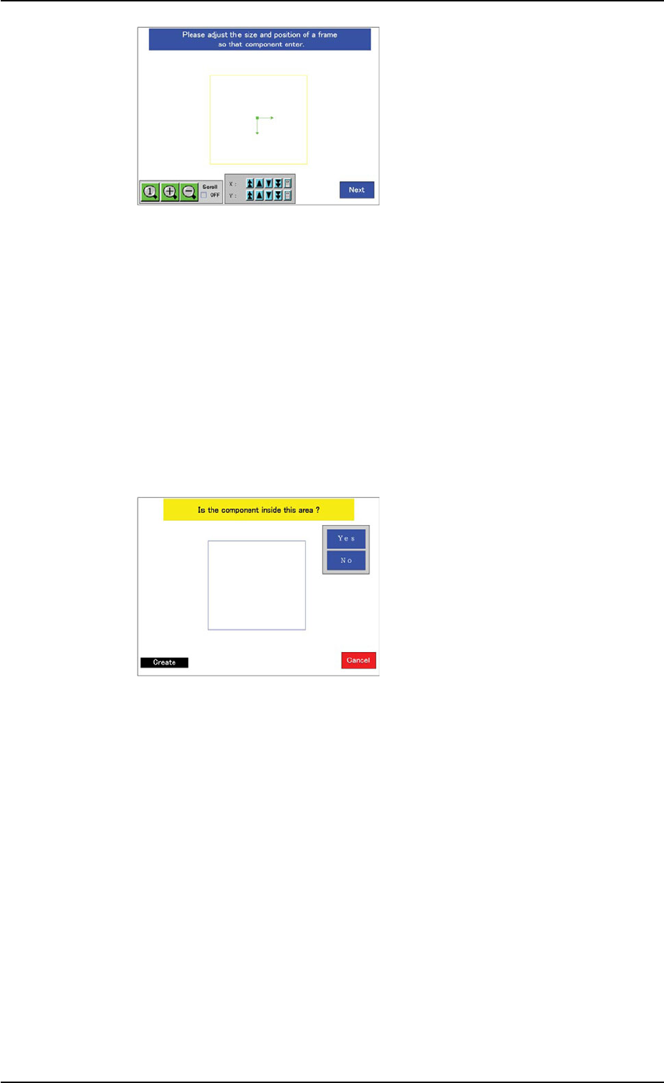
(11) Specify the direction in
which the image is protrud-
ing from the light blue frame
(diffusion plate).
When a component shape
other than "Leaded" is se-
lected, this window does not
open.
Instead, the window in Step
(12) opens.
(12) When the component shape
belongs to "Leaded", select
the side(s) where the leads
are connected and the direc-
tion of the leads.
When the component shape
belongs to "Area Array", se-
lect the type of electrodes.
The lighting pattern will be
changed according to the
selection.
When the component shape belongs to "Leadless", this window
does not open.
Instead, the window in Step (13) opens.
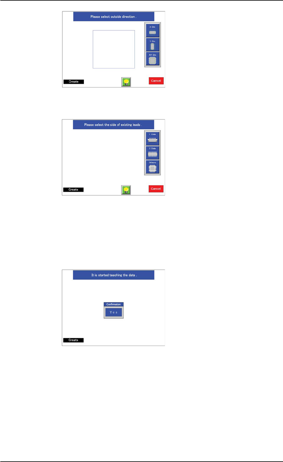
(13) Perform the teaching opera-
tion as follows.
Press the [Yes] button.
When the component shape
belongs to "Leaded" and the
lead arrangement is "Com-
plex" or the large view func-
tion is selected and the out-
line of the component image
is protruding from the diffu-
sion plate (the [No] button
selected in Step (10)), only
the mold teaching operation
is performed and a window
opens, enabling the opera-
tor to confirm if the mold size
and outward length of the
component are correctly
taught or not.
Fig. 2F99
Fig. 2F100
Fig. 2F101