2OM-1075-002.pdf - 第149页
AHB01ESPP Fig. 2E13 "Opn. Mode" T ab Sheet *7 Recog Monitor Display Mode It can be specified how to display the results of recognition such as P .E.C. and component recognition functions. Mode Specify the recog…

AHB01ESPP
[Nozzle Exchange] Button
When this button is pressed, the "Nozzle Exchange" edit win-
dow opens. Set the rate of speed reduction in the data entry field
for a series of operations performed when the nozzle is changed.
[Nozzle Rotation] Button
When this button is pressed, the "Nozzle Rotation" edit window
opens. Set the rate of speed reduction in the data entry field for
the nozzle rotation.
[Nozzle Change] Button
When this button is pressed, the "Nozzle Change" edit window
opens. Set the rate of speed reduction in the data entry field for
the nozzle change operation.
(a) If a higher speed than that specified in this tab sheet is set
in the component library data, it is regulated to the speci-
fied upper limit.
(b) If a lower speed than that specified in this tab sheet is set
for some components in the component library data, it
becomes valid.
(c) When there is still some room in the placement tact time
according to the line balance, the machine can be oper-
ated at a slow tact time specified by this function.
[Tray Elevator] Button
Refer to the instruction manual of the multi-layer tray feed-
ers (option) for details.
[Tray Traverse] Button
Refer to the instruction manual of the multi-layer tray feed-
ers (option) for details.
*5 [Next] Button
When pressed, this button opens the second page.
*6 [Set] Button
After setting various operation modes, press the [Set] button. The
specified data is saved.
When the machine is set in the "RUN" or the "WAIT" mode, the
setting operation cannot be performed.
The setting operation is possible only when the machine is in
the "STOP" mode.
0206-003 5-20
3.3 "Opn. Mode" Tab
Note
Note
AHB01ESPP
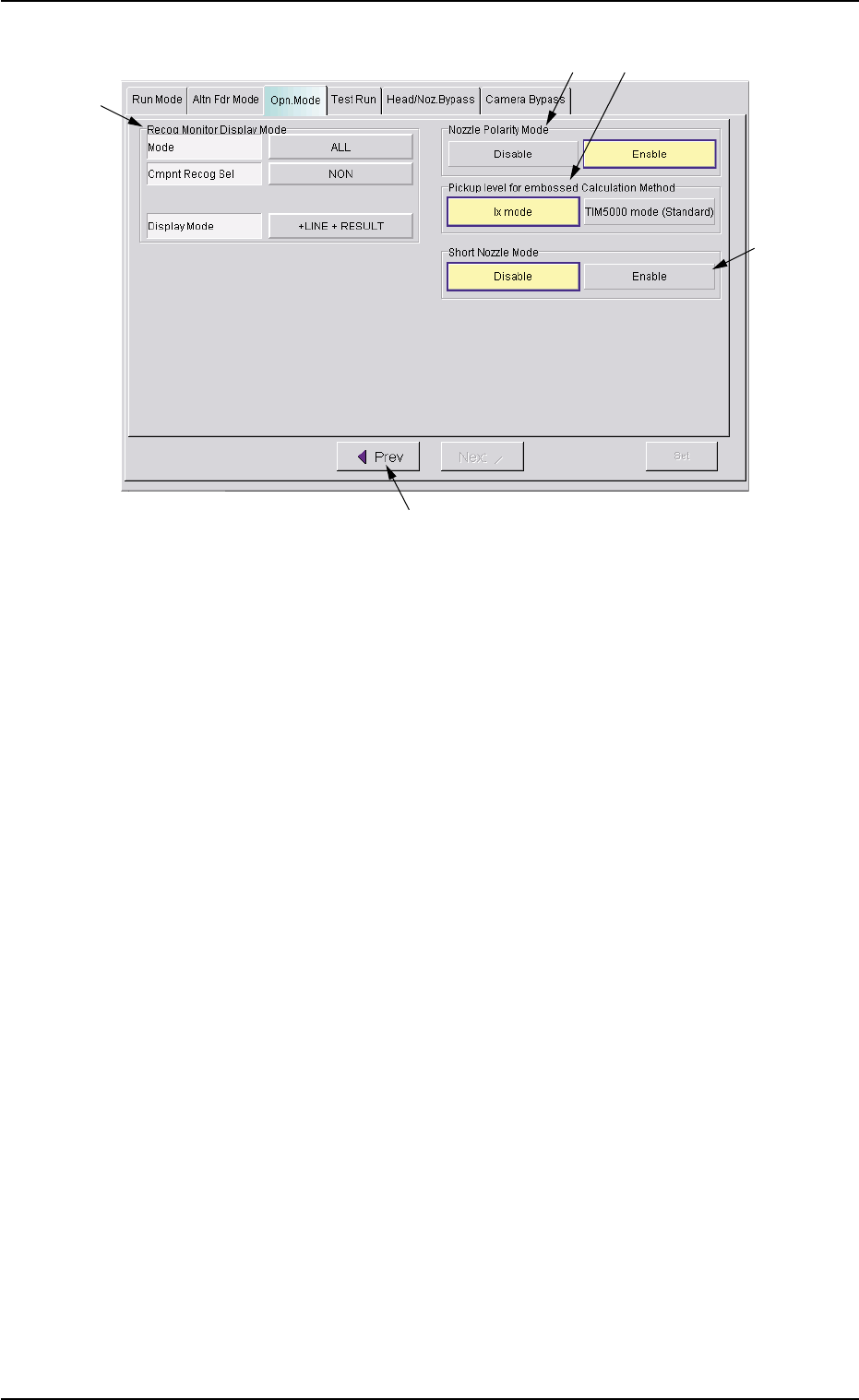
Fig. 2E13 "Opn. Mode" Tab Sheet
*7 Recog Monitor Display Mode
It can be specified how to display the results of recognition such as
P.E.C. and component recognition functions.
Mode
Specify the recognition mode which the displayed result should
be based on.
Every time the right button is pressed, the label changes in scroll-
ing such as "ALL" Æ "DEVICE" Æ "P.C.B.".
"ALL" : When this is selected, the results of the com-
ponent and P.E.C. recognition operations are
regarded as object items to be displayed.
"DEVICE" : When this is selected, the results of the com-
ponent recognition operation are regarded as
object items to be displayed.
"P.C.B." : When this is selected, the results of the P.E.C.
recognition operation are regarded as object
items to be displayed.
Cmpnt Recog Sel
When the results of the component recognition operation are
regarded as object items to be displayed (when [ALL] or [DE-
VICE] is selected for "Mode"), it is required to specify the condi-
tion (requirements) for the component recognition.
Every time the right button is pressed, the label changes in scroll-
ing such as "NON" Æ "CAMERA" Æ "PARTS" Æ "FEEDER".
"NON" : There is no condition (requirements) for com-
ponent recognition.
0308-004 5-21
3.3 "Opn. Mode" Tab
*7
*8
*11
*10
*9

AHB01ESPP
"CAMERA" : It is required to specify a camera ID.
When the [CAMERA] button is selected, the
[CAMERA ID] button appears under the se-
lected button.
Every time the [CAMERA ID] button is pressed,
the label of the right button changes in scroll-
ing such as "CAM-A1" Æ "CAM-B1" Æ "CAM-
A2" Æ "CAM-B2" Æ "CAM-M1" Æ "CAM-M2".
"PARTS" : It is required to specify a component ID.
When the [PARTS] button is selected, the
[PARTS ID] button appears under the selected
button.
When the [PARTS ID] button is pressed, the
"PARTS ID" edit window opens. Enter the com-
ponent ID to be specified.
"FEEDER" : It is required to specify a feeder No.
When the [FEEDER] button is selected, the
[FEEDER No.] button appears under the se-
lected button.
When the [FEEDER No.] button is pressed,
the "FEEDER No." edit window opens. Enter
the feeder No. to be specified.
Display Mode
Set the condition to display the recognition results of the compo-
nent recognition.
Every time the right button is pressed, the label changes in scroll-
ing such as "NON" Æ "+LINE" Æ "+LINE + RESULT".
[NON] : Only the outline of the recognized component is
displayed.
[+LINE] : The outline of the recognized component and a
crosshair are displayed.
[+LINE+RESULT] : The outline of the recognized component, a
crosshair, and the result of the recognition (the
coordinates of the crosshair center) are dis-
played.
3.3 "OPN. Mode" Tab
0308-004 5-22