2OM-1075-002.pdf - 第190页
AHB01ESPP 6 . 1 "Device Err" T ab The corresponding tab sheet enables the operator to check the date & time of error occurrence, error IDs, error description, error codes, etc. • Sheet Layout When the "…
AHB01ESPP
• Window Composition
*1 Tabs and Tab Sheets
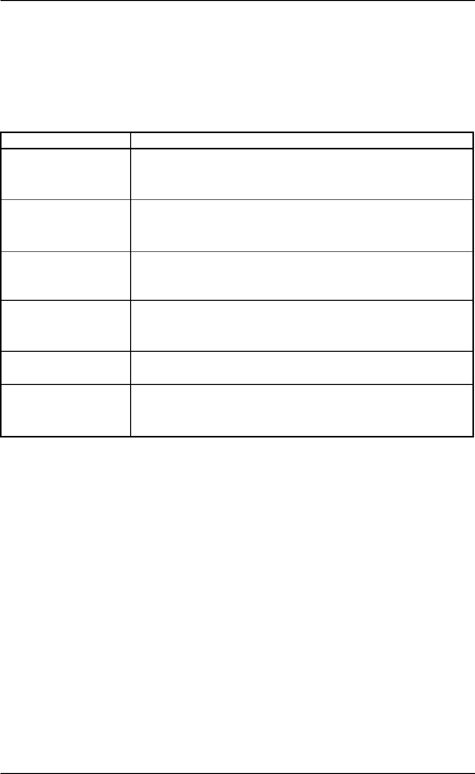
The "RECALL" window is provided with the following 6 tabs. When
a tab is pressed, the corresponding tab sheet appears inside the
window.
Table 2E7
Tabs Description
Device Err The corresponding tab sheet enables the operator to check the date
& time of error occurrence, error items, error description, informa-
tion IDs, and user names.
Handling Err The corresponding tab sheet enables the operator to check the er-
ror-caused feeder Nos., the date & time, information IDs, and error
description.
Machine Info The corresponding tab sheet enables the operator to check the date
& time of message issuance, device status, information IDs, the con-
tents of message, and user names.
Comp. Recog. Err The corresponding tab sheet enables the operator to check the date
& time of component recognition error occurrence, information IDs,
and error description.
Servo Alarm The corresponding tab sheet enables the operator to recall the hys-
teresis of errors for individual types of servo alarm.
Recog. Image The corresponding tab sheet enables the operator to save the recog-
nized images of component recognition errors on a floppy disk (in-
serted into the drive on the service panel).
0308-004 5-27
6. "RECALL" Window (Submenu)
AHB01ESPP
6.1 "Device Err" Tab
The corresponding tab sheet enables the operator to check the date &
time of error occurrence, error IDs, error description, error codes, etc.
• Sheet Layout
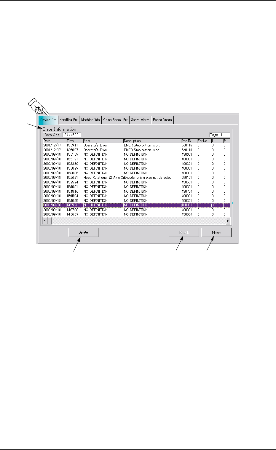
When the "Device Err" tab is pressed in the "RECALL" window
(submenu), the following tab sheet appears inside the window.
Fig. 2E25 "Device Err" Tab Sheet
• Sheet Composition
*1 Error Information
The following items are displayed with respect to device error.
Data Cnt : Displayed in the text box is the number of device er-
rors retained in the current memory area per maxi-
mum retainable errors. The numerator shows the
number of retained errors and the denominator the
maximum number of retainable errors in memory.
Date : Displayed is the date of error occurrence.
Time : Displayed is the time of error occurrence.
Item : Displayed are the types (classification) of errors.
Description: Displayed is the description of errors.
Info. ID : Displayed is the error IDs.
Fdr. No. : Displayed are the feeder Nos.
6.1 "Device Err" Tab
0308-004 5-28
*1
*2
*3
*4
AHB01ESPP
U:Displayed are the unit Nos.
P:Displayed are the P-Nos. of the placement data (P-
data).
O:Displayed are the O-Nos. of the placement data (O-
data).
Head : Displayed are the head Nos.
Nozzle : Displayed are the nozzle Nos.
Camera : Displayed are the camera Nos.
Stocker : Displayed are the stocker Nos. (3 digits) where the
nozzles on the head are removed.
1 1 0
Nozzle Stocker Address (1 to 10)
Nozzle Stocker (1 to 4)
1: Stocker A1 (Option)
2: Stocker A2 (Option)
3: Stocker B1
4: Stocker B2
Tray : Displayed are the tray step Nos.
Block : Displayed are the tray block Nos.
ID : Displayed are the component IDs.
Dt : Displayed are the codes that classify the errors in
detail.
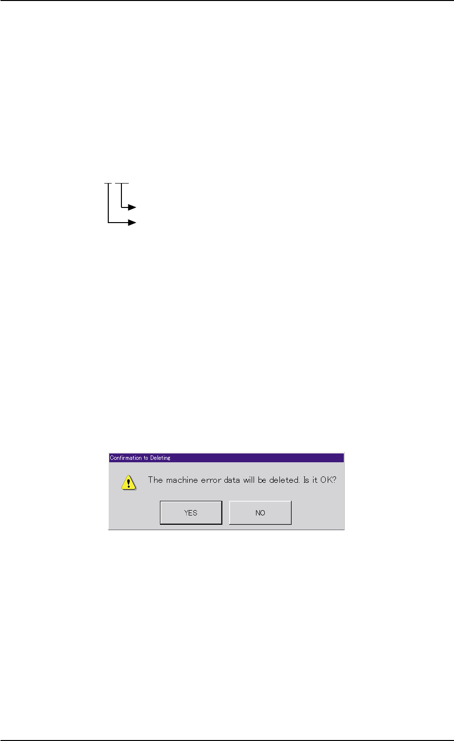
*2 [Delete] Button
When this button is pressed, the following dialog box opens for con-
firmation to deletion.
Fig. 2E26 "Confirmation to Deleting" Dialog Box
When the [YES] button is pressed, the device error data is deleted.
When the [NO] button is pressed, the dialog box closes without de-
leting the device error data.
*3 [Back] Button
When this button is pressed, the previous list of errors (previous
details) is displayed.
*4 [Next] Button
When this button is pressed, the next list of errors (next details) is
displayed.
0308-004 5-29
6.1 "Device Err" Tab