2OM-1075-002.pdf - 第353页
AHB01ESPP 5.2.5 "T each Library (New)" Sheet • • • • • Sheet Layout When the [Set] button is pressed in the "Set Initial Data (New)" sheet, the following sheet appears inside the tab sheet. Fig. 2F86 …

AHB01ESPP
*6 [Edit Data] Button
When pressed, this button makes it possible to correct the param-
eters for the selected component ID.
*7 [Delete Test ID] Button
When pressed, this button makes it possible to delete the test ID
(selected from the "Test ID List (XXXX)" list box).
*8 [Entry Comp ID] Button
When pressed, this button makes it possible to register the test ID
(selected from the "Test ID List (XXXX)" list box) in the component
library.
*9 [Entry Test ID] Button
When pressed, this button makes it possible to register the compo-
nent ID (selected in the "Component Library" selection window) in
the "Test ID List (XXXX)" list box.
Operation Procedure
(1) Select the component ID to be tested from the "Test ID List (XXXX)"
list box.
(2) Press the [Select] button.
The library data for the selected component ID is regarded as the
data to be set initially.
5.2 Library Teaching
0206-003 6-120
AHB01ESPP
5.2.5 "Teach Library (New)" Sheet
••
••
• Sheet Layout
When the [Set] button is pressed in the "Set Initial Data (New)" sheet,
the following sheet appears inside the tab sheet.
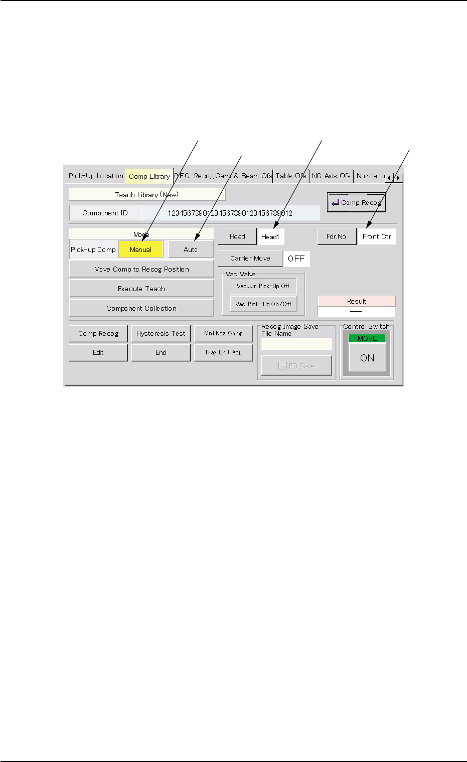
Fig. 2F86 Sheet for Execution of Teaching Function (Component Pick-Up)
5.2.5.1 Component Pick-Up
The component to be taught must be picked up from the selected feeder.
••
••
• Automatic Operation
Operation Procedure
(1) Attach a nozzle, using the "Nozzle Change" sheet.
Attach the nozzle selected in the component library for the compo-
nent to be taught.
(2) Set a parameter in the "Fdr. No." text box.
Refer to the placement feeder location data or manually enter a pa-
rameter.
(3) Press the [Auto] button (beside the label "Pick-up Comp").
5.2 Library Teaching
0206-003 6-121
Manual Component
Attachment
Component Pickup
from Feeder
Designation of
Head No.
Designation of
Feeder No.

AHB01ESPP
(4) Press the [ON] button (entitled "MOVE"). In two seconds, press the
[ENABLE] button on the operation panel.
A component is picked up from the specified feeder and shifted to
the area above the fixed recognition camera.
(5) Press the [Move Comp to Recog Position] button.
(6) Press the [ON] button (entitled "MOVE"). In 2 seconds, press the
[ENABLE] button on the operation panel.
The component is shifted to the area above the fixed recognition
camera.
••
••
• Manual Operation
Operation Procedure
(1) Set "Front Ctr" or "Rear Ctr" in the "Feeder No. Set" text box.
(2) Press the [Manual] button (beside the label "Pick-up Comp").
(3) Press the [ON] button (entitled "MOVE"). In 2 seconds, press the
[ENABLE] button on the operation panel.
(4) Set the [OPERATION] switch to the "SETUP" side and press the
[READY] button to turn off the LED.
(5) Open the safety door.
(6) Attach the component to be taught manually (by hand) to the vacuum
nozzle.
Every time the [Vac Pick-Up On/Off] button in the "Vac Valve"
group box is pressed, the vacuum nozzle can be turned
"ON" or "OFF".
When the nozzle is turned "OFF", note that the component
will fall down.
(7) Close the safety door.
(8) Set the [OPERATION] switch to the "RUN" side and press the
[READY] button to turn on the LED.
(9) Press the [Move Comp to Recog Position] button.
(10)Press the [ON] button (entitled "MOVE"). In 2 seconds, press the
[ENABLE] button on the operation panel.
The component is shifted to the area above the fixed recognition
camera.
5.2 Library Teaching
Note
0206-003 6-122