2OM-1075-002.pdf - 第80页
2 . 4 Preparation for Nozzles It must be confirmed that the nozzle IDs in the current pattern program are registered in the placement head/nozzle data. After the confirma- tion, it is required to set all nozzles to be us…

2. Preparation for Program Change Operation
2.1 Preparation for Component Library
Library data must be created for new components when there is no
component library data required to create a pattern program.
(a) Refer to "Section 3 Component Library" in "Vol. 3: Program-
ming and Machine Data" for how to navigate through the
window.
(b) Refer to another instruction manual "Component Library
(TIM-X Series)" for how to create the data.
2.2 Creation of Pattern Program for Production
Model
A pattern program is required for automatic operation.
Refer to "Section 2 Pattern Programs" in "Vol. 3: Programming and Ma-
chine Data" for details.
2.3 Registration of Pattern Program for Production
Model
The pattern program and the component library data can be sent from
the network terminal (option) to the machine side.
2. Preparation for Program Change Operation
01 12-002 3-2 AHB01ESPP
Note
2.4 Preparation for Nozzles
It must be confirmed that the nozzle IDs in the current pattern program
are registered in the placement head/nozzle data. After the confirma-
tion, it is required to set all nozzles to be used in the nozzle stocker.
Be sure to attach the nozzles correctly in place.
When a nozzle is attached incorrectly (not to the place
specified in the nozzle data), it may cause undesir-
able interference.
Operation Procedure
(1) Check the nozzle IDs in the "Nozzle" column of the placement feeder
location data in the current pattern program.
(2) Check the placement head/nozzle data. When the nozzle IDs are
not registered, search them in the list of nozzle types and register
them.
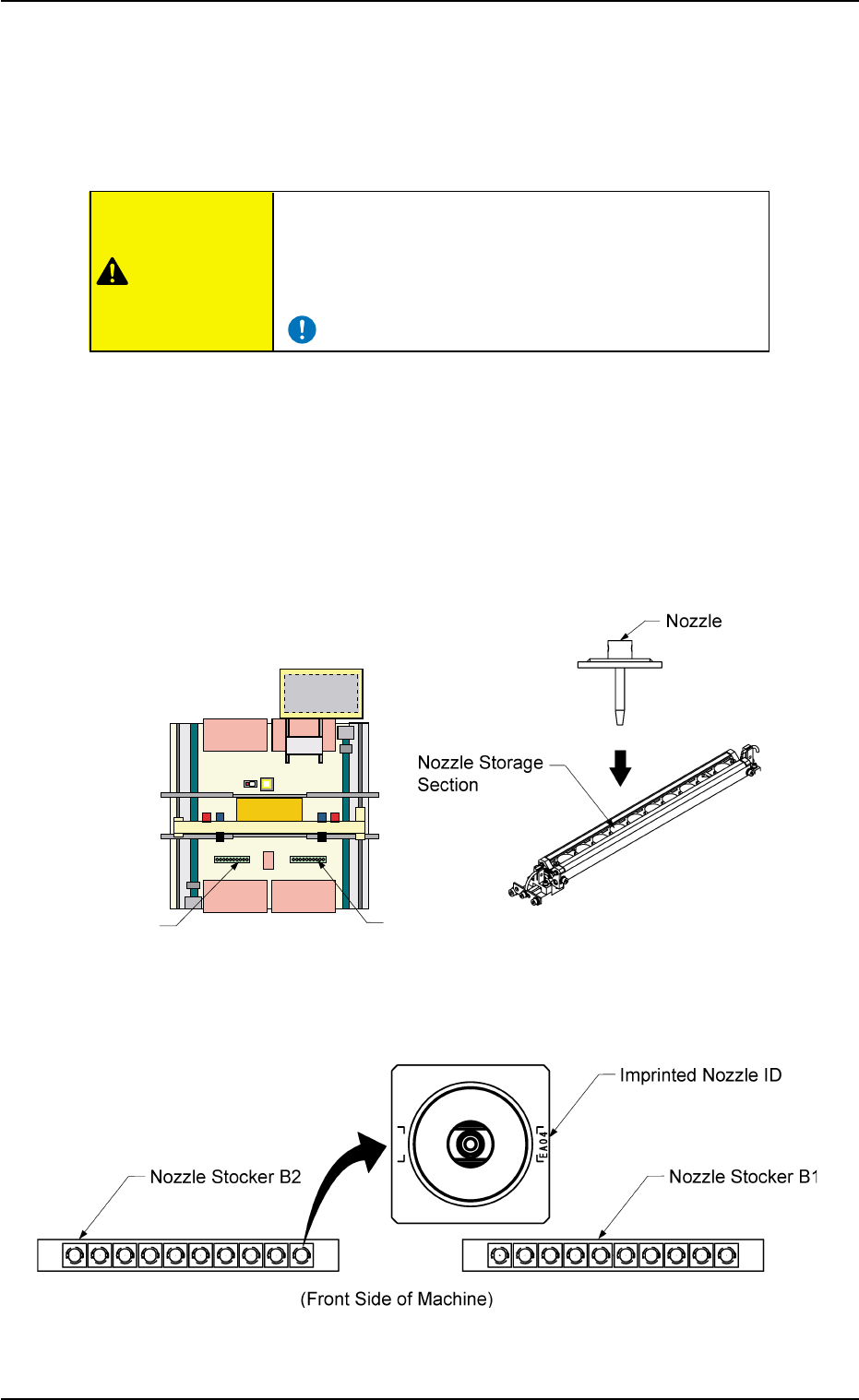
(3) Set all nozzles to be used in the nozzle stockers.
Direct the inprinted nozzle ID mark as shown in the figure and insert
the nozzle into the groove.
Fig. 2C2-1 Nozzle Stocker Position Fig. 2C2-2 Rough View of Nozzle Stocker
Fig. 2C2-3 Direction of Nozzle Arrangement
0308-004 3-3
AHB01ESPP
2.4 Preparation for Nozzles
Nozzle Stocker B1
Nozzle Stocker B2
Rear Side of Machine
Front Side of Machine
CAUTION
(a) Refer to "3. "Nozzle Data" Window" in "Section 5" of "Vol.
3: Programming and Machine Data" for details.
(b) It is recommended for better efficiency that the nozzles for
Head #1 be stored in Nozzle Stocker B1 and the nozzles
for Head #2 in Nozzle Stocker B2.
Do not put any foreign substance on the nozzle
stocker section.
Otherwise, the machine will break down.
• Keep the diffusion plates of the vacuum nozzles
clear of oil, nicks, etc.
Otherwise, an error may occur during component
recognition.
• Do not bring a magnet close to any vacuum
nozzle.
Otherwise, an error may occur during component
picks and placement.
0308-004 3-4 AHB01ESPP
2.4 Preparation for Nozzles
CAUTION
CAUTION
Note