2OM-1075-002.pdf - 第272页
AHB01ESPP • Operation for Implementation of Component Recognition A component recognition can be performed. Component Recognition (1) When the [Comp Recog (Manual)] button is pressed in the "Com- ponent Recog. T est…
AHB01ESPP
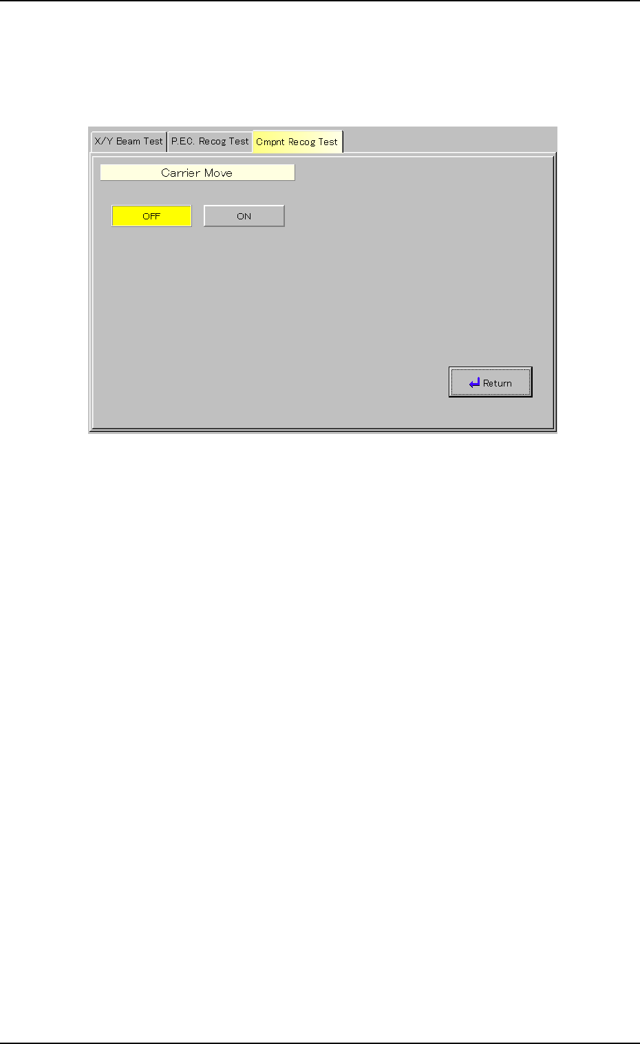
(5) Setting of Carrier Movement Operation
(5-1) When the [Carrier Move] button (*9) is pressed in the "Com-
ponent Recog. Test" sheet (Fig. 2F22), the following "Carrier
Move" sheet appears.
Fig. 2F34 "Carrier Move" Sheet
(5-2) Press the [OFF] or the [ON] button.
3.3 "Cmpnt Recog Test" Tab
0206-003 6-39
AHB01ESPP
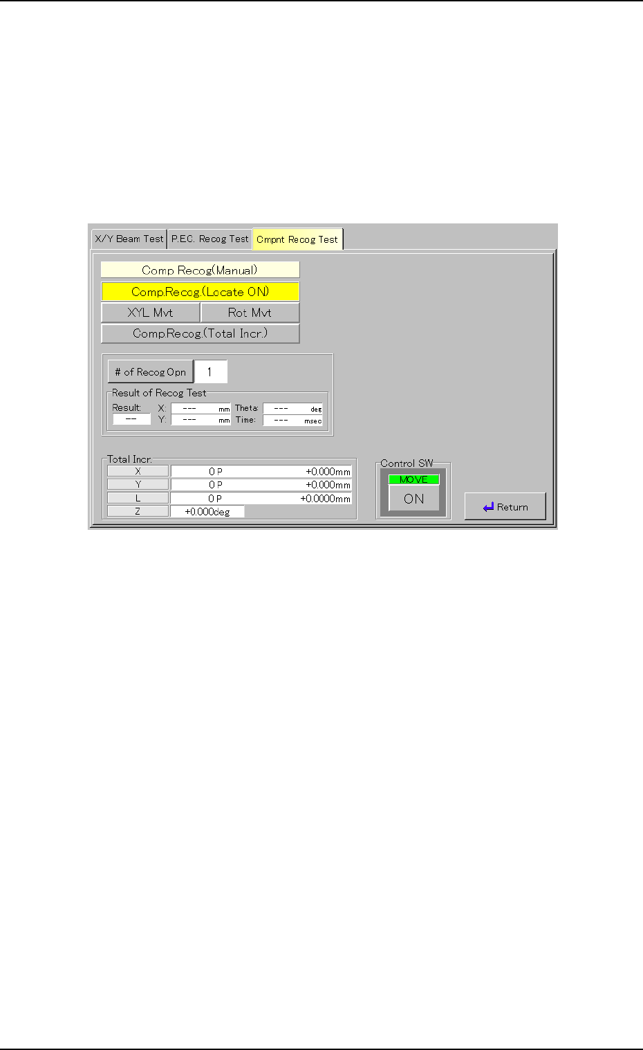
• Operation for Implementation of Component Recognition
A component recognition can be performed.
Component Recognition
(1) When the [Comp Recog (Manual)] button is pressed in the "Com-
ponent Recog. Test" sheet, the "Comp Recog (Manual)" sheet ap-
pears.
Fig. 2F35 "Comp Recog (Manual)" Sheet (Component Recognition)
(2) Set the number of recognition times.
Press the [# of Recog Opn] button. The "# of Recog Opn" window
opens. Enter the number of recognition times and press the [Set]
button.
(3) When the [ENABLE] button on the operation panel is pressed in 2
seconds after the [ON] button (entitled "MOVE"), a component rec-
ognition is implemented.
(4) When the [Return] button is pressed, the "Component Recog. Test"
sheet appears.
0308-004 6-40
3.3 "Cmpnt Recog Test" Tab
AHB01ESPP
• Procedure for Component Recognition Test
The following methods are provided to conduct a component recog-
nition test.
• Component Recognition Test on Manually Attached Component
• Component Recognition Test on Automatically Picked Component
from Each Feeder
The following describes how to use each method.
Procedure for Component Recognition Test on Manually Attached
Component
A component cannot be attached manually on the front side of
the machine.
Be sure to attach a component manually on the rear side of the
machine.
(1) Press the [Test ID] button (*4) in the "Component Recog. Test" sheet
(Fig. 2F22). The "Test ID Set" sheet appears.
Register the component ID to be tested as a test ID.
(2) Check the parameter in the text box (*6) and attach the specified
nozzle.
Attach the nozzle in the "Nozzle Set/Reset" sheet.
Refer to "4.4 "Nozzle Change" Tab" for details.
(3) Press the [Fdr. No.] button (*5). The "Fdr. No." sheet appears.
Set the feeder No. so that the installed feeder is not located at the
position where it does not set in the way of manual component at-
tachment.
In normal cases, the [Front Ctr] button should be selected.
(4) Press the button (*2). The sheet appears.
Select the head that is provided with the nozzles on the operation
side.
(5) Press the button (*3). The sheet appears.
Select the camera to capture an image.
(6) Press the button (*9). The sheet appears.
Select the [ON] button to use the function.
(7) Select the [Vacuum Pick-Up Off] button in the "Vac Valve" group box
(*10).
(The vacuum valve is turned "ON" automatically.)
When the vacuum valve is kept "ON" (component pickup
condition), the previous sheet cannot be resumed.
(8) Press the [Pick from Fdr (Mnl)] button and then the [ON] button (en-
titled "MOVE"). After that, press the [ENABLE] button on the opera-
tion panel in 2 seconds.
The head moves to the position of the specified feeder No. and the
vacuum valve is turned "ON" automatically.
(9) Set the [OPERATION] switch on the operation panel to the "SETUP"
side.
Note
0206-003 6-41
3.3 "Cmpnt Recog Test" Tab
Note
Note