2OM-1075-002.pdf - 第52页
1 . 2 Component Placement (starting with preparation for component picks) The X/Y beams are provided with placement heads that have nozzles on them. The nozzles pick up components and place them on the P .C.B.’s. Fig. 2B…
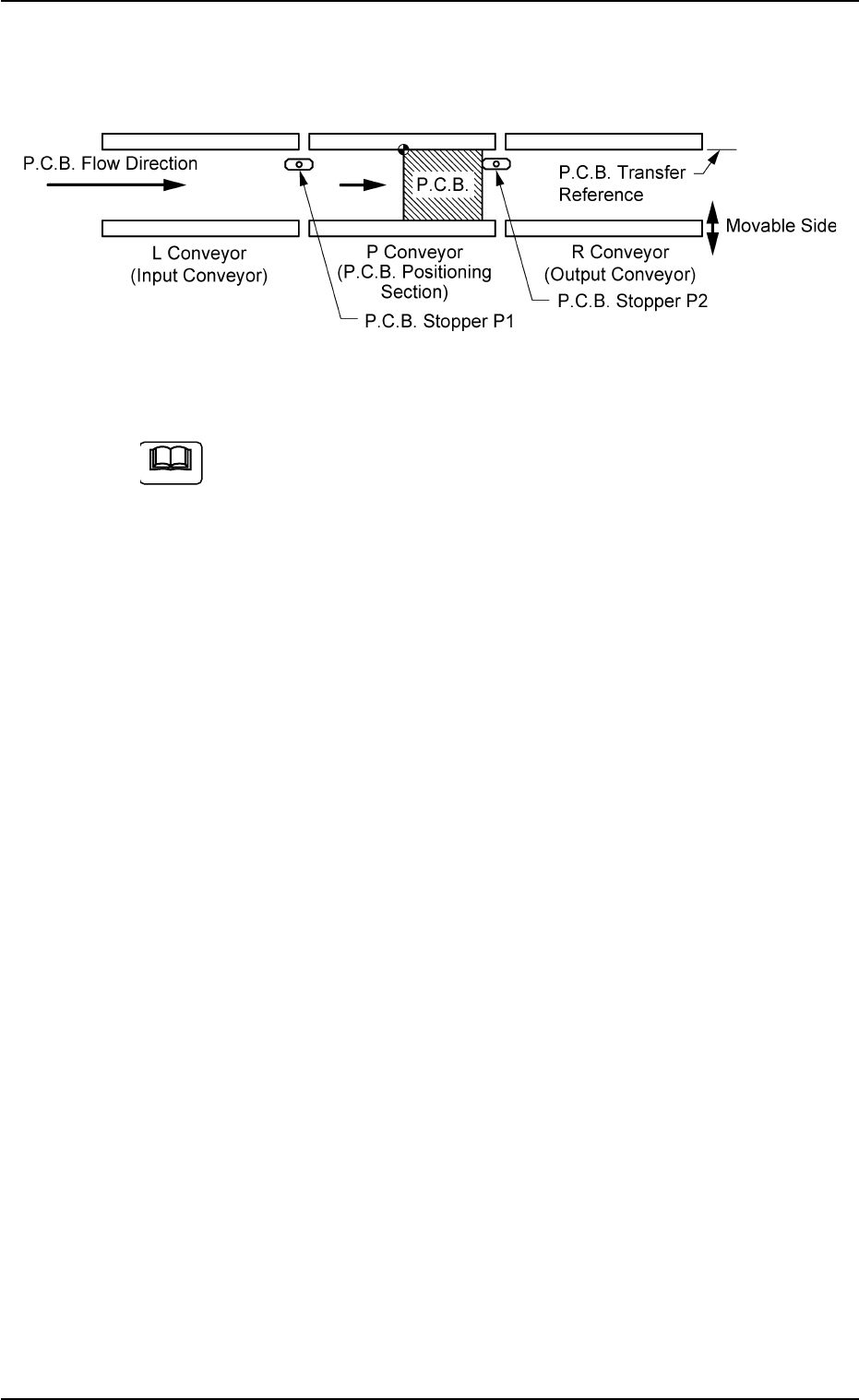
(3) The P.C.B. is clamped by the clamping plate and the pusher on the
P.C.B. positioning section.
Fig. 2B3
The reference pin for positioning is aligned with the P.C.B. hole
position to position the P.C.B.’s.
The sequence is determined as follows.
Backup Plate Upward Movement
(Stop at the place where the clearance between the P.C.B. and
the chute is "0.5 mm")
Clamp Plate Upward Movement + Backup Plate Upward Move-
ment
Positioning Completed
0206-003 2 -2
AHB01ESPP
1.1 P.C.B. Transfer and Positioning
Note
1.2 Component Placement (starting with preparation
for component picks)
The X/Y beams are provided with placement heads that have nozzles
on them. The nozzles pick up components and place them on the
P.C.B.’s.
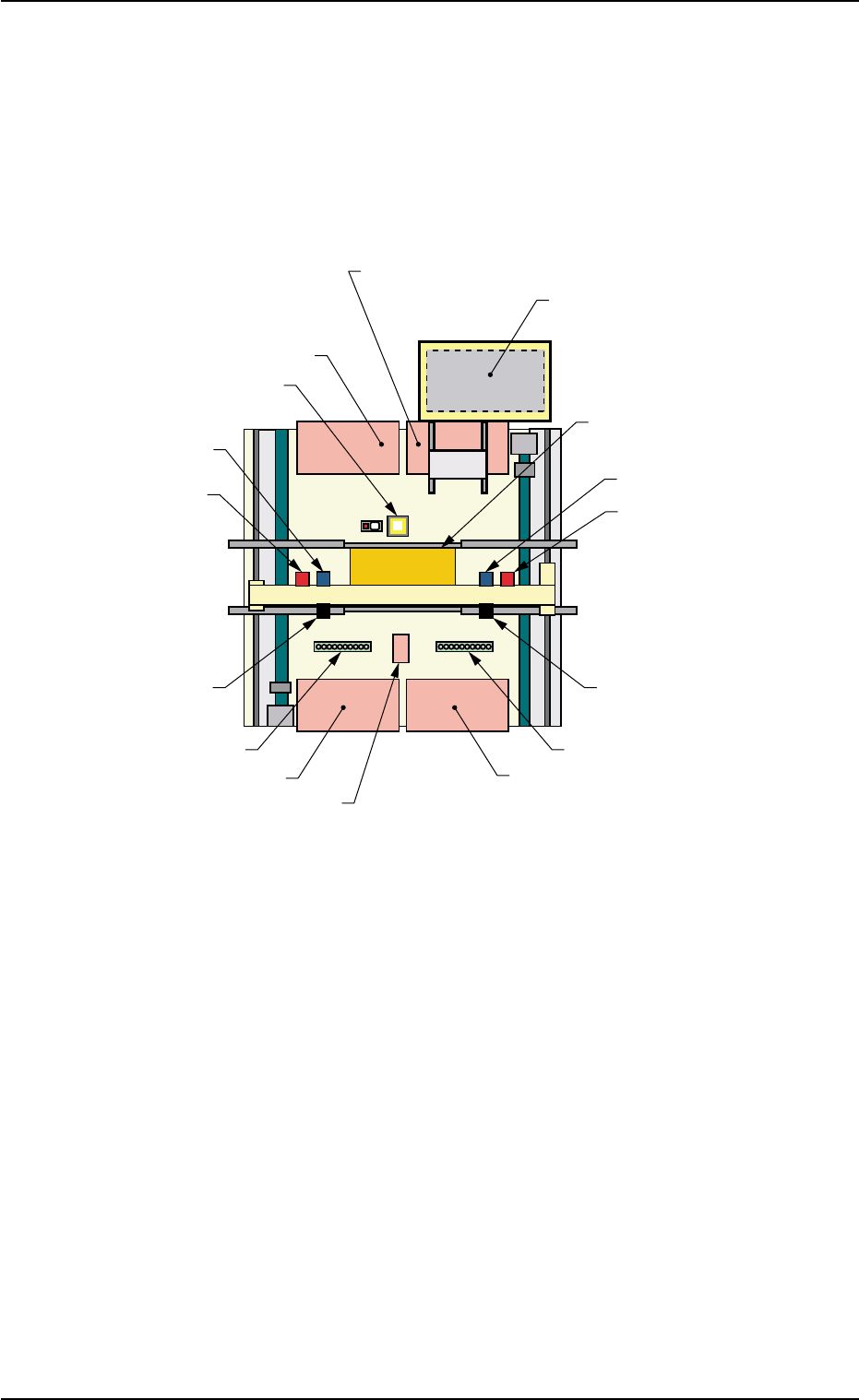
Fig. 2B4 Location of Each Unit (Provided with Multi-Layer Tray Feeder 2)
Scope Reference Item Nos.
P.C.B. Positioning Section and Nozzle Stockers:
Preparation for Component Picks (1.2.1)
Each Feeder and Feeder Base:
Component Supply and Picks (1.2.2)
Movable and Fixed Cameras, Component Storage Box:
Preparation for Component Placement (1.2.3)
P.C.B. Positioning Section:
Component Placement (1.2.4)
0206-003 2 -3
AHB01ESPP
1.2 Component Placement (starting with preparation for component picks)
Feeder Base #2 (Option)
Feeder Base #1
Feeder Base #4
Feeder Base #3
Fixed Camera A1
Head #2
P.E.C. Recognition
Camera 2
Head #1
P.E.C. Recognition
Camera 1
P.C.B. Positioning Section
(P Conveyor)
Movable Camera 2
Movable Camera 1
Nozzle Stocker B2
Nozzle Stocker B1
Component Storage Box
Multi-Layer Tray Feeder 2
(Option)
1.2.1 Preparation for Component Picks
P.C.B. Positioning Section:
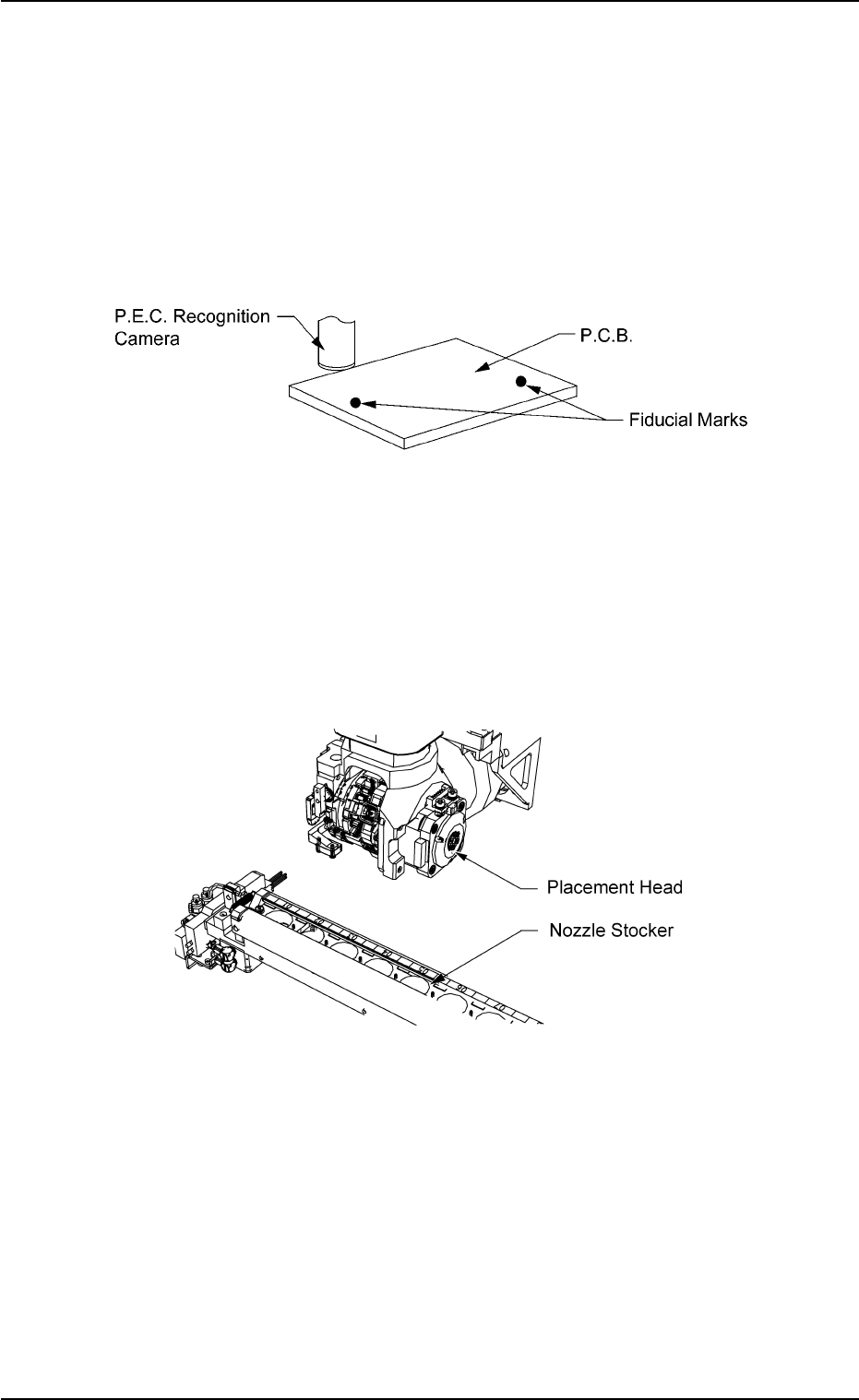
P.E.C. Recognition (Recognition of Placement Position)
• The P.E.C. camera is used to detect through P.E.C. recognition if
the placed components are shifted from the correct position or not.
Note: This will be performed only when specified in the pattern
program.
Fig. 2B5 P.E.C. Recognition
Nozzle Stocker: Nozzle Change
• A vacuum nozzle is selected for components and the attached
nozzle is replaced with the proper one.
The vacuum nozzle on the placement head is stored in the nozzle
stocker and the required one is taken out of the stocker.
Fig. 2B6 Nozzle Change
0206-002 2 -4 AHB01ESPP
1.2 Component Placement (starting with preparation for component picks)