2OM-1075-002.pdf - 第362页
AHB01ESPP The window in Step (14) opens. When the component shape belongs to "Area Array", the large view function is used, and the outline of the component is protruding from the diffusion plate (the [No] butt…
AHB01ESPP
0308-004 6-129
5.2 Library Teaching
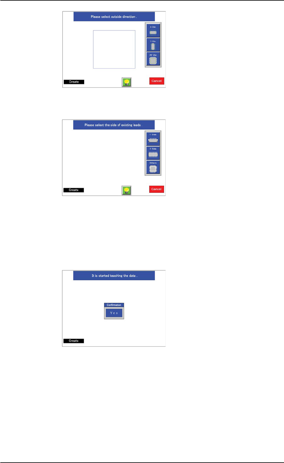
(11) Specify the direction in
which the image is protrud-
ing from the light blue frame
(diffusion plate).
When a component shape
other than "Leaded" is se-
lected, this window does not
open.
Instead, the window in Step
(12) opens.
(12) When the component shape
belongs to "Leaded", select
the side(s) where the leads
are connected and the direc-
tion of the leads.
When the component shape
belongs to "Area Array", se-
lect the type of electrodes.
The lighting pattern will be
changed according to the
selection.
When the component shape belongs to "Leadless", this window
does not open.
Instead, the window in Step (13) opens.
(13) Perform the teaching opera-
tion as follows.
Press the [Yes] button.
When the component shape
belongs to "Leaded" and the
lead arrangement is "Com-
plex" or the large view func-
tion is selected and the out-
line of the component image
is protruding from the diffu-
sion plate (the [No] button
selected in Step (10)), only
the mold teaching operation
is performed and a window
opens, enabling the opera-
tor to confirm if the mold size
and outward length of the
component are correctly
taught or not.
Fig. 2F99
Fig. 2F100
Fig. 2F101
AHB01ESPP
The window in Step (14) opens.
When the component shape belongs to "Area Array", the large view
function is used, and the outline of the component is protruding
from the diffusion plate (the [No] button selected in Step (10)), a
window opens, enabling the operator to enter the mold size of the
component.
The window in Step (15) opens.
In a case other than the above-described ones, the window in Step
(17) opens.
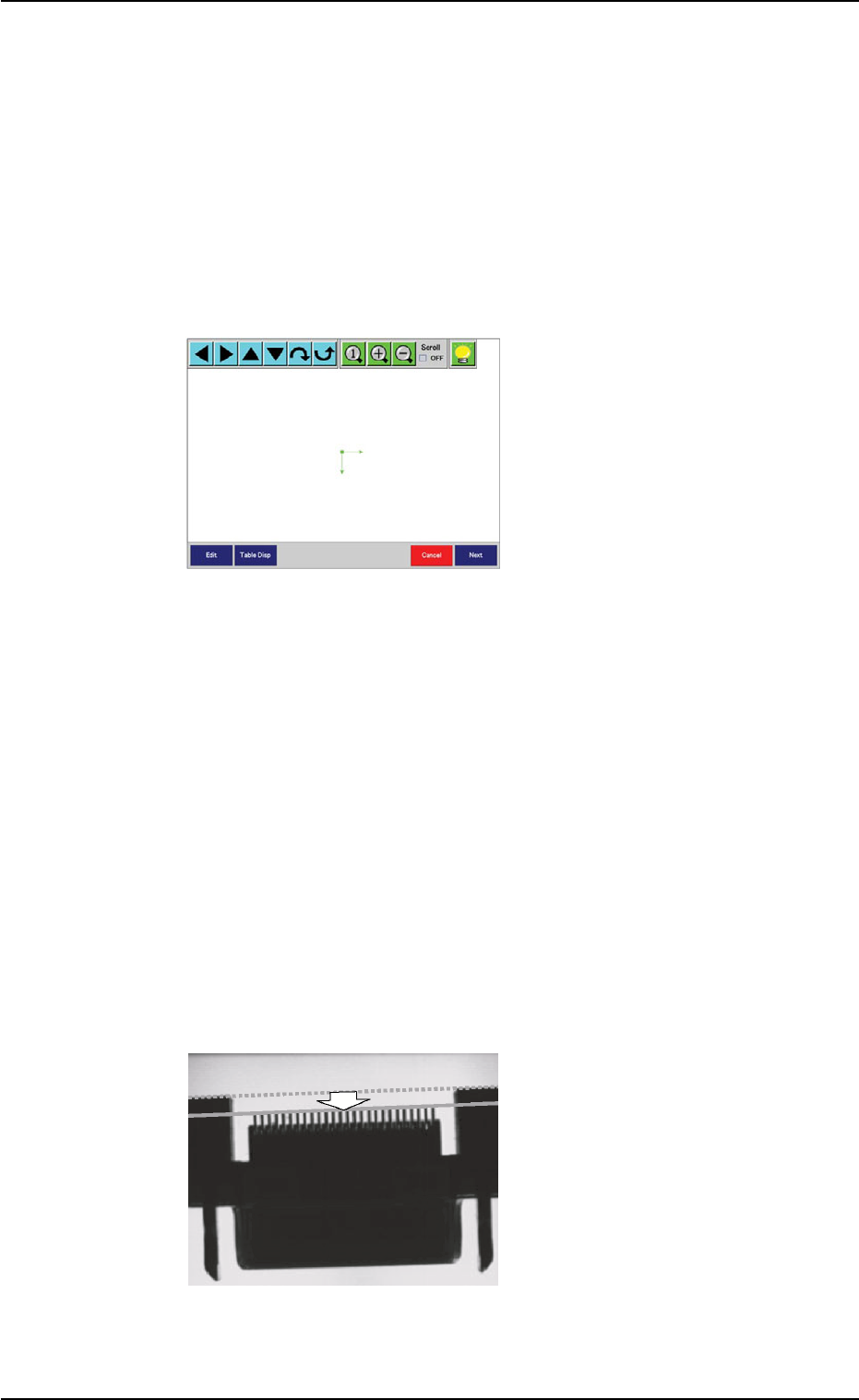
(14) Confirm that the mold size
and outward length of the
component are correctly
specified.
If not, press the [Edit] or the
[Table Disp] button for the
correction.
When the component shape
belongs to "Leaded" and the
outward length does not
match the detected end of
the arrayed leads, the lead
teaching operation may not
be successful.
In this case, align the outward length once with the end of the ar-
rayed leads as shown in the figure and perform the lead teaching
operation. After that, reset the changed outward length to the origi-
nal one.
When no problem arises, press the [Next] button.
The lead teaching operation starts.
When "Simple" is selected for "Lead Arrangement" in Step (5), the
window in Step (17) opens.
When "Complex" is selected, the window in Step (16) opens.
Fig. 2F102
Fig. 2F103
0308-004 6-130
5.2 Library Teaching
AHB01ESPP
(15) Enter the mold size with the
[Edit] or the [Table Disp] but-
ton, adjust the position and
angle of the graphic roughly,
and press the [Next] button.
The ball teaching operation
starts.
The window in Step (17)
opens.
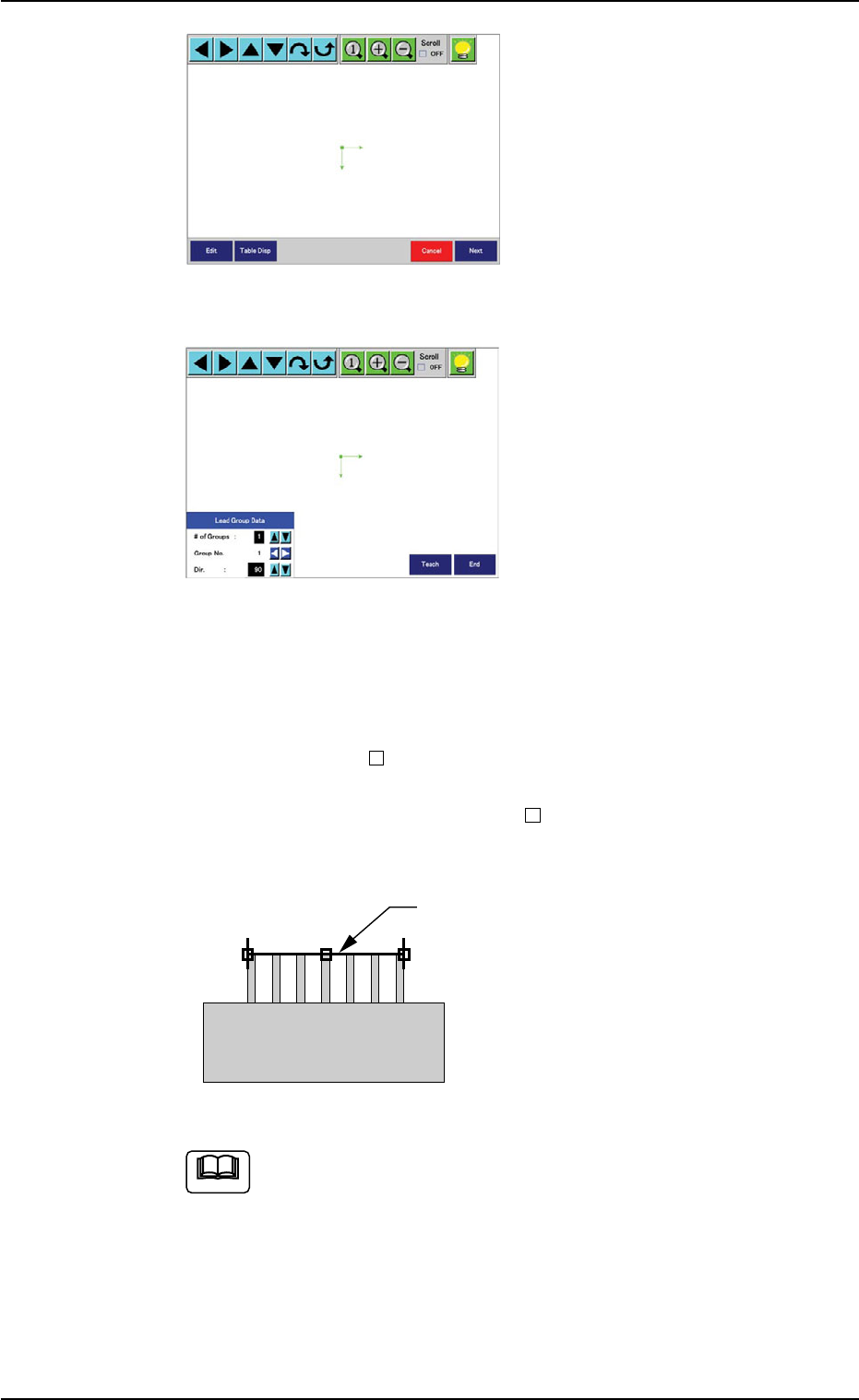
(16) A window for partial lead
teaching operations opens.
This window makes it pos-
sible to perform teaching
operations on each lead
group.
First of all, set the number
of lead groups to be regis-
tered. (Up to 8 groups)
Then, select the group No.
(starting with "1" in normal
cases) and the direction of
the lead groups to be regis-
tered.
Click the hot spots "
" located at the left, right, and central sides
of the yellow ruler and align the ruler with the ends of the arrayed
leads (lead group). The right and left
must be aligned with the
leads located at both ends of the group.
Press the [Teach] button.
Up to 4 lead types can be registered. However, when more
than 5 groups are taught and the lead types are all differ-
ent (regarded as different data), it means that more than 4
types are handled and no data will be saved for any groups
exceeding the maximum number of types.
In this case, the message "Since the num of lead types
was reached 5 (Max:4), the taught data has not been
saved." is issued.
Fig. 2F104
Fig. 2F104-1
Ruler
Fig. 2F104-2
Note
0308-004 6-131
5.2 Library Teaching