2OM-1075-002.pdf - 第83页
3 . 2 Setting of P .C.B. Support Pins The P .C.B. support pins are used to keep the upper surface of the P .C.B. in proper height for stabilization of the machine. 3.2.1 Setting of P .C.B. Support Pins in "PCB Suppo…
3. Program Change Operation
3.1 Selection of Current Pattern Program
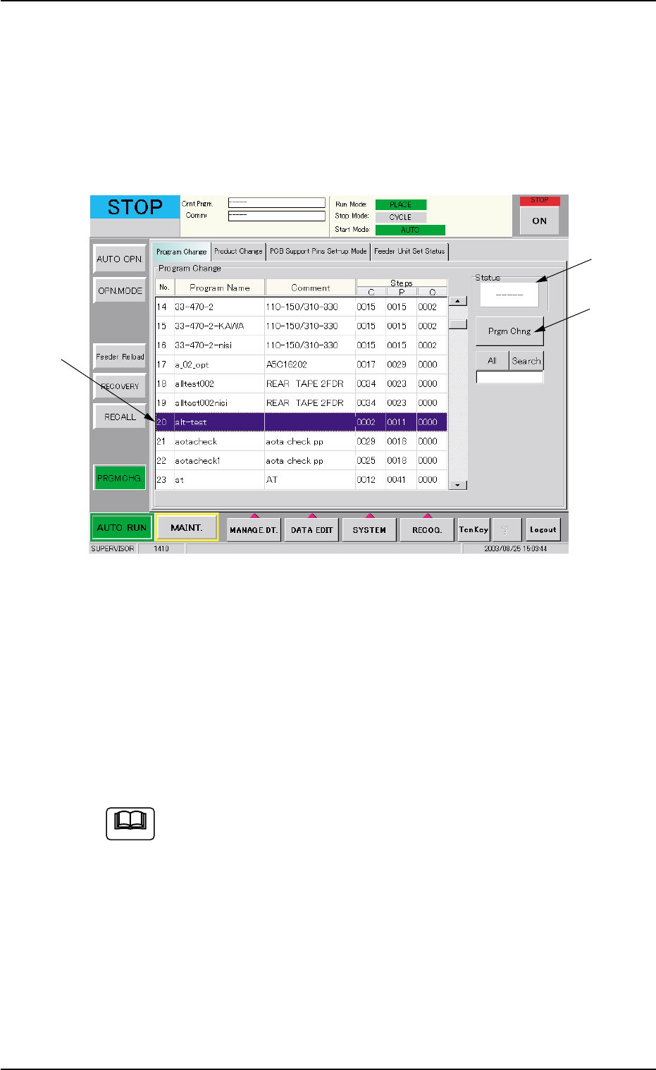
A pattern program must be selected as a current one in the "Program
Change" tab sheet of the "PRGM. CHG." window (submenu).
Fig. 2C3 "Program Change" Tab Sheet
Operation Procedure
(1) Select the program name to be set as a current one from the "Pro-
gram Change" list (*1). The line turns blue, indicating that the pat-
tern program is selected.
(2) Press the [Prgm Chng] button (*2). "OK" appears in the "Status"
box (*3), indicating that the selected program was downloaded nor-
mally.
When the selected pattern program has an error and "NG" ap-
pears in the "Status" box, the program change is not imple-
mented. In such a case, correct the pattern program and re-
implement the program change operation.
3. Program Change Operation
0308-004 3-5 AHB01ESPP
*2
*3
*1
Note
3.2 Setting of P.C.B. Support Pins
The P.C.B. support pins are used to keep the upper surface of the P.C.B.
in proper height for stabilization of the machine.
3.2.1 Setting of P.C.B. Support Pins in "PCB Support Pins Set-up
Mode" Tab Sheet
Starting Condition: • All devices must be zeroed.
• The safety doors must be closed.
• The lamp of the [READY] button must be "ON"
(beam current supplied).
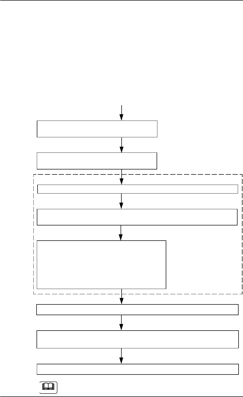
Menu Selection in "PCB Support Pins Set-up
Mode" Tab + [ON] Button (entitled "MOVE")
The X/Y beam is automatically moved to the
shelter position (the rear side).
Set the [OPERATION] switch on the front operation panel to the "SETUP" side.
Press the [READY] button on the front operation panel to turn off the electro-
magnetic lock of the front safety door.
Open the front safety door and attach the P.C.B.
support pins.
As for the setup procedure of the P.C.B. support
pins, follow the same procedure as described in
"To set up the P.C.B. support pins with power
turned OFF".
Close the front safety door and set the [OPERATION] switch to the "RUN" side.
Press the [READY] button on the front operation panel to turn on the electro-
magnetic lock of the front safety door.
Zero all devices.
Refer to "7.3 "PCB Support Pins Set-up Mode" Tab" in "Section 5" for the
detailed information on how to set up the P.C.B. support pins.
3.2 Setting of P.C.B. Support Pins
"SETUP"
Side
• Conveyor Width Maximum
Sequential Operation ON/
OFF
• The sequential operation "ON"
or "OFF" of the backup base
upward movement can be se-
lected.
This mode enables the
operator to make avail-
able the menus for vari-
ous operations related to
the surrounding devices
of the conveyors.
0107-001 3 -6 AHB01ESPP
Note
3.2.2 Setting of P.C.B. Support Pins with Power "OFF"
The load power to the motors, etc., is shut off but the
setting operation must be performed carefully, protect-
ing your hands from moving mechanisms.
Operation Procedure
(1) Check the condition of the P.C.B.’s to be handled.
(Check the size and thickness of the P.C.B.’s and whether or not
components are previously placed on the back.)
(2) Determine whether or not the set-up operation must be performed.
• When the set-up operation is not required (the same condition as
that of the current production can be applied), perform the pro-
gram change operation for the automatic operation.
• When the set-up operation is required (different condition from
that of the current production), proceed to Step (3).
(3) Stop the operation and set the power breaker crank to "OFF".
To prevent the power breaker crank from being set to
"ON" by mistake, lock the crank using a padlock kept
by the person in charge.
(4) Open the front safety door and detach all feeders.
(5) Move the X/Y beam to the rear side.
(6) Remove the P.C.B. support pins.
Otherwise, the movable chute will collide with the P.C.B. support
pins when the set-up operation is performed.
Refer to "3.2.3 Setting of P.C.B. Support Pins and Precautionary
Items on Detachment" for details.
(7) Check that a P.C.B. support pins, etc., is not left behind on the backup
table.
Check that no component or dust, etc., has fallen into the holes on
the backup table.
(8) Close the front safety door and set the power breaker to "ON".
(9) After zeroing, set up the conveyor width.
Refer to "7.2 "Product Change" Tab" in "Section 5" for details.
(10) Follow the procedure similar to Step (3) and turn off the power.
(11) Open the front safety door and push the X/Y beam back to the rear
side.
(12) Insert the P.C.B. support pins vertically into the holes on the backup
table.
Be sure to insert the pins such that they are dispersed equally over
the whole area of the P.C.B. to be used
0308-002 3-7
AHB01ESPP
3.2 Setting of P.C.B. Support Pins
CAUTION
CAUTION
Note