2OM-1075-002.pdf - 第32页
Registered Number of T est Library Data Up to 100 pieces Ref.: The taught component library data can be saved in the network terminal (option). Notes: (a) The above number of registered library data is based on the case …
28. Specifications When a program change is made, the P.C.B. transfer conveyor width
of Automatic and the P.C.B. support pin’s up/down movement are automatically set
Setup Function up.
Minimum Unit of Movement
P.C.B. Transfer Conveyor Width : 0.1 mm
(Resolution: 0.0025 mm/pulse)
P.C.B. Support Pin Up/Down : 0.005 mm
(Resolution: 0.005 mm/pulse)
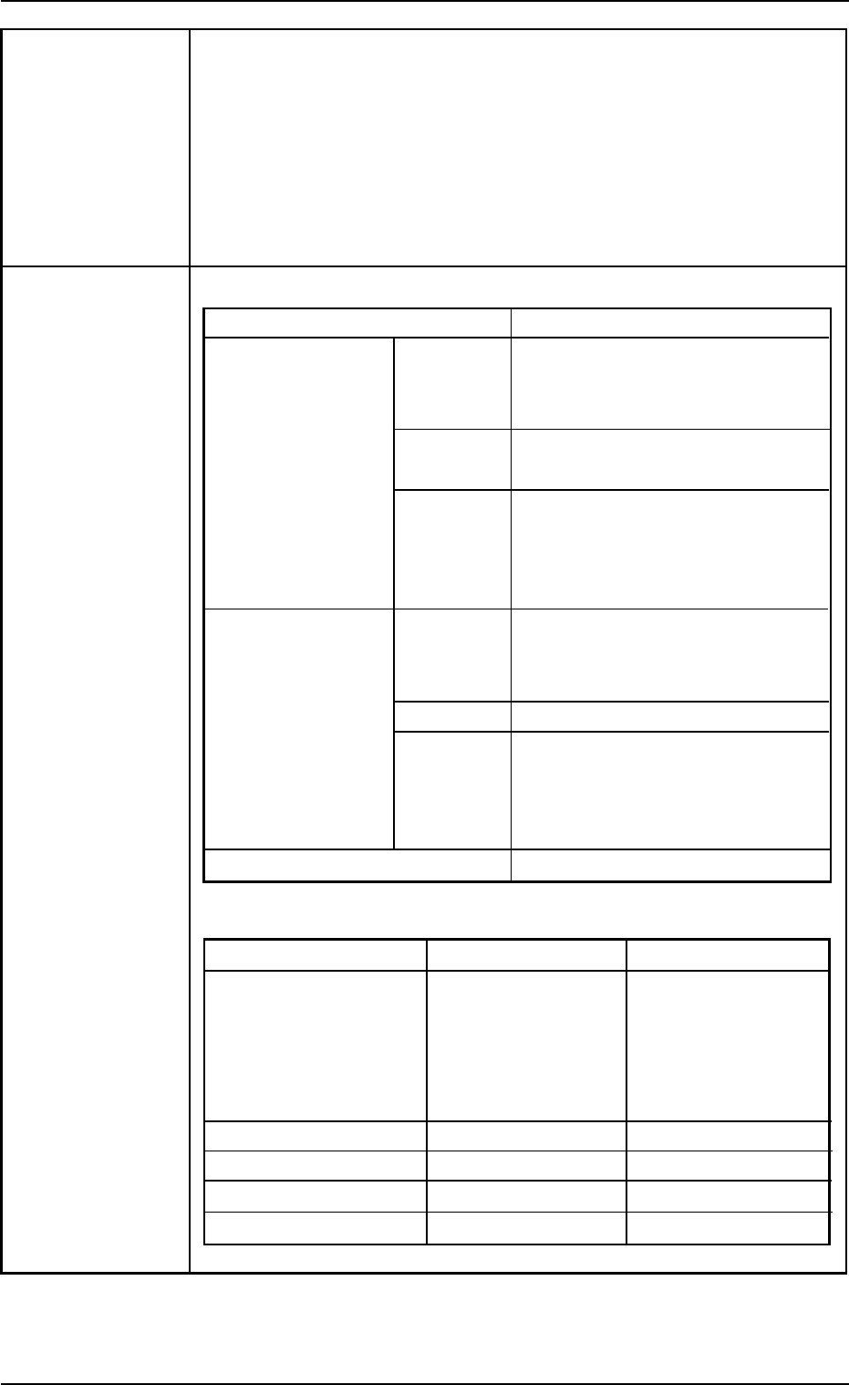
29. Teaching of Applicable Component Shapes
Component
Library Data
2. Specifications
Component Shape Applicable Components
Leadless Cylindrical
Components
Square
Deform
Leaded IC
Connectors
Others
Area Array BGA and LGA Components
Size of Applicable Components
Small View (mm) Large View (mm)
Outer Dimensions 1.0 × 0.5 2.0 × 1.2
to 18 × 18 to 55 × 55
(Max. 100 × 26)
See Note a below.
Minimum Lead Pitch 0.3 0.4
Minimum Lead Width 0.1 0.18
Minimum Ball Diameter 0.2 0.4
Minimum Ball Pitch 0.3 0.55
(Note: The component
thickness should
be 5 or less.)
Cylindrical Components
Resistors, Capacitors, Di-
odes, etc.
Square Components
Resistors, Capacitors, etc.
Deformed Components
Aluminum Electrolytic Capaci-
tors, Tantalum Capacitors,
Variable Resistors, etc.
ICs
SOP, QFP, SOJ, and PLCC,
etc.
Connectors
Leaded components other than
those described above
Mini-Mold Transistors, Coils,
etc.
0206-003 1-14 AHB01ESPP
Registered Number of Test Library Data
Up to 100 pieces
Ref.: The taught component library data can be saved in the network
terminal (option).
Notes: (a) The above number of registered library data is based on the
case where the connectors are used.
(b) The data for the BGA/CSP components exceeding "18 ×
18 mm" is created semi-automatically. (Manual Input of
Each Parameter)
(c) Automatic teaching operation may not be performed,
depending on the types (shapes) of components and
leads. In this case, it is required to manually enter or
correct the parameters.
• The molded part of a component is formed round or al-
most looks round.
• The molded part is formed by a complex polygon.
(Components (shapes) equivalent to "Deform (Complex)")
• The shape of the leads or the electrodes is not rectangu-
lar.
• Prominently poor contrast in the leads or the electrodes.
• Components having protruding portions in the mold at both
ends of the arrayed leads.
• Components having several types of leads or whose leads
are arrayed in complexity.
• Area array components whose balls cannot be grouped
(d) It is impossible to automatically teach the data for the vacuum
nozzles being used for component picks, the vacuum
nozzles not used for component picks, or the portion where
the image of a component is laid over the hole of the diffu-
sion plate.
It is required to manually correct the parameters that could
not be taught automatically.
(e) When a component stays completely inside the silhouette
of the vacuum nozzle (viewed through the back lighting),
the automatic teaching operation cannot be performed.
The automatic teaching operation cannot be performed
either, depending on the combination of a special vacuum
nozzle type and the component to be taught.
30. Power Supply 200±20 V AC, 3-Phase, 50/60 Hz
Connected to the power supply unit (3-phase 4-wire system)
(One of the four wires is used as a ground wire.)
31.Apparent Power Approx. 5 kVA
2. Specifications
0206-003 1-15 AHB01ESPP
32. Air Pressure Supply 0.49 to 0.69 MPa (5 to 7 kgf/cm
2
)
Pressure
Set 0.4 MPa (4.1 kgf/cm
2
)
Pressure Note: The air pressure of 0.4 MPa (4.1 kgf/cm
2
) or more is
required during operation.
• Use the following dry and clean air.
Moisture : Dew Point -17°C or lower (Atmospheric Pressure)
Oil : 0.1 mg/m
3
or less (ANR)
Dust : Solid Material 0.01 µm or less
33. Air Approx. 20 L/min (Standard Condition)
Consumption
34. Vacuum -93 kPa (70 cmHg)
Pressure
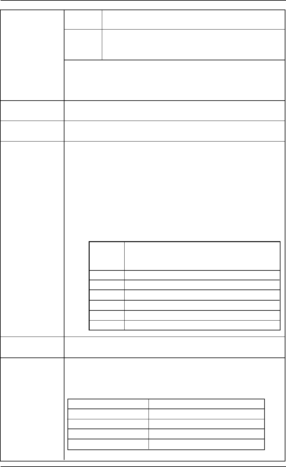
35. Environmental Temperature: 20±10°C
Condition Humidity : 30 to 80% (Avoid dew condensation.)
Note : When the ambient temperature rises more than the surface of the
machine, dew may condense under the condition described be-
low.
Note that dew condensation may cause the machine to break down.
Condition of Dew Condensation
Dew may condense when the differences (based on "Humidity
(%)") between the ambient and surface temperatures of the ma-
chine reach the values or more in the table below.
Humidity Differences between Ambient and Surface
(%) Temperatures of Machine
(Ambient Temperature > Surface Temperature)
80 3°C or more
70 6°C or more
60 8°C or more
50 10°C or more
40 14°C or more
30 18°C or more
36. Dimensions Approx. 1,550 (width) × 1,995 (depth) × 1,450 (height) mm
Note: The height becomes 2,100 mm when the light tower is included.
37. Mass 1,670 kg (excluding the feeders )
Note: The mass changes depending on the type of feeders to be installed.
Mass of Options (For Reference)
Name Mass (kg)
Tape Feeder The mass depends on feeder types.
Vibratory Stick Feeder Approx. 6.5/unit
Attachment Approx. 9/unit
Multi-Layer Tray Feeder Approx. 130/unit
Note: The mass related to components is not included.
2. Specifications
0206-003 1-16 AHB01ESPP