2OM-1075-002.pdf - 第212页
AHB01ESPP (2) Select the [ON] button (entitled "MOVE") and press the [ENABLE] button on the operation panel in 2 seconds. The conveyor width is changed to the target one. (3) When the conveyor width must be adj…
AHB01ESPP
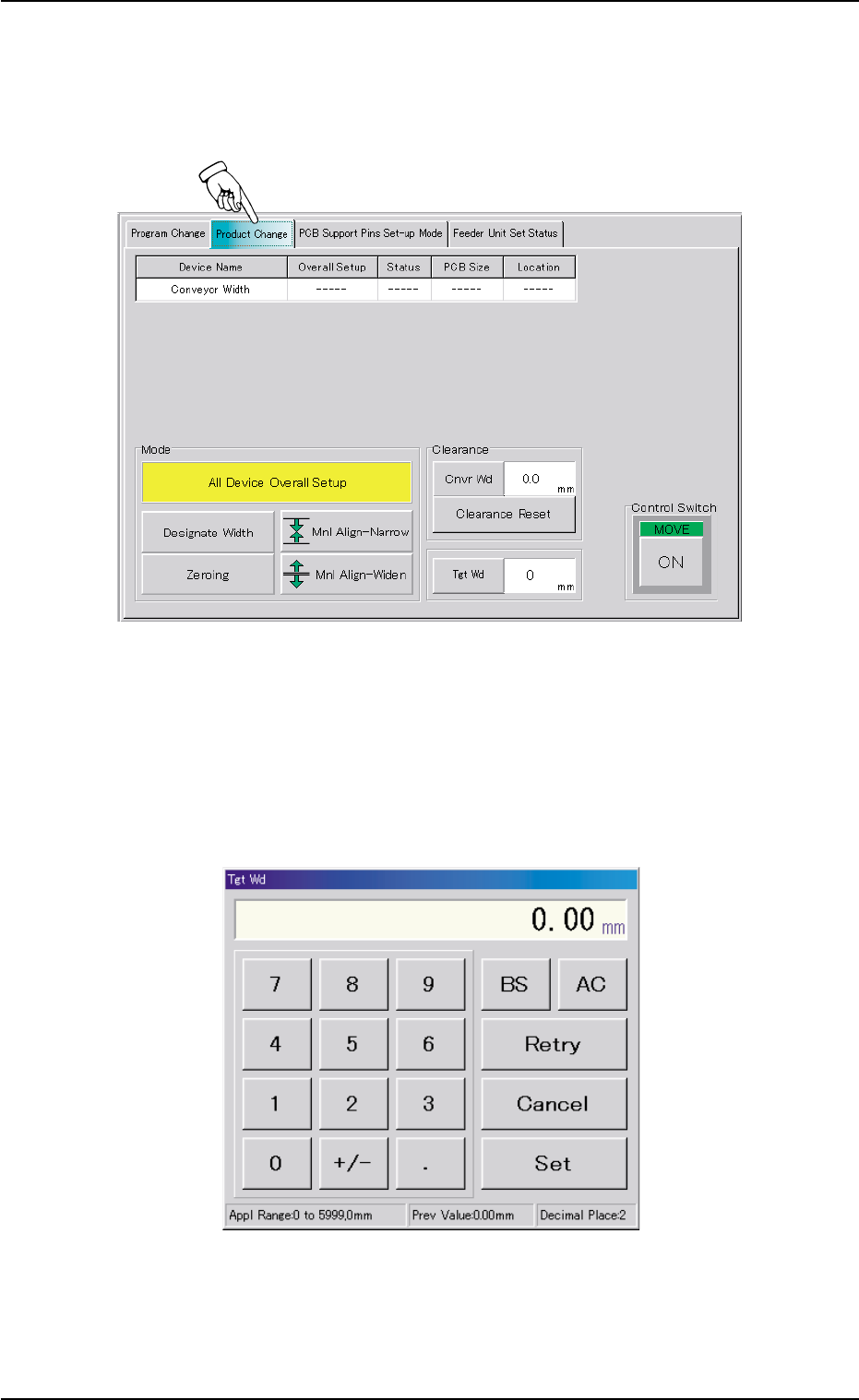
7.2.2 Conveyor Width Setup Operation
Follow the steps below to perform a setup operation for the conveyor
width.
Fig. 2E41 "Product Change" Tab Sheet for "X/Y Table Chute Width"
Operation Procedure
(1) Press the [Tgt Wd] button to open the "Tgt Wd" edit window. Enter a
target value and press the [Set] button. The target value will be speci-
fied.
Fig. 2E42 "Tgt Wd" Edit Window
7.2 "Product Change" Tab
0206-003 5-49

AHB01ESPP
(2) Select the [ON] button (entitled "MOVE") and press the [ENABLE]
button on the operation panel in 2 seconds. The conveyor width is
changed to the target one.
(3) When the conveyor width must be adjusted according to the result
of P.C.B. transfer check operation, select the [Mnl Align-Narrow] or
the [Mnl Align-Widen] button and press the [ON] button (entitled
"MOVE"). After that, press the [ENABLE] button on the operation
panel in 2 seconds.
The manual alignment operation for the conveyor width is imple-
mented in the "Narrow" or "Wide" direction as long as the [ENABLE]
button is held down.
(4) To update the clearance data after the completion of the adjustment,
press the [Clearance Reset] button.
"Clearance" is changed to "Current Width - P.C.B. Size Y (Width)".
Note: When the data exceeds "±5.0 mm", this operation becomes
unavailable.
7.2 "Product Change" Tab
0107-001 5-50
AHB01ESPP
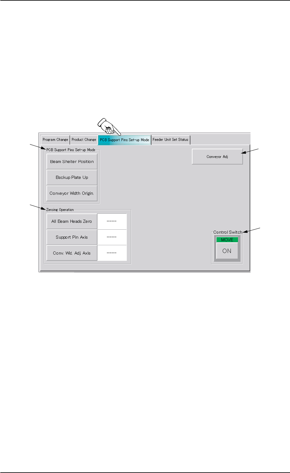
7.3 "PCB Support Pins Set-up Mode" Tab
The corresponding tab sheet enables the operator to set the environ-
mental condition required to specify the positioning of the P.C.B. sup-
port pins.
••
••
• Sheet Layout
When the "PCB Support Pins Set-up Mode" tab is pressed in the "PRGM.
CHG." window (submenu), the following tab sheet appears inside the
window.
Fig. 2E43 "PCB Support Pins Set-up Mode" Tab Sheet
••
••
• Sheet Composition
*1 "PCB Support Pins Set-up Mode" Group Box
The following buttons are provided in this group box.
[Beam Shelter Position] Button
Select the [Beam Shelter Position] button and press the [ON]
button (entitled "MOVE"). After that, press the [ENABLE] but-
ton on the operation panel in 2 seconds. The X/Y beam es-
capes back to the rear side.
[Backup Plate Up] Button
Select the [Backup Plate Up] button and press the [ON] but-
ton (entitled "MOVE"). After that, press the [ENABLE] button
on the operation panel in 2 seconds. The backup plate starts
moving up.
7.3 "PCB Support Pins Set-up Mode" Tab
*1
*4
*2
*3
0206-003 5-51