2OM-1075-002.pdf - 第400页
AHB01ESPP 5 . 9 "Head Center Ofs" T ab The corresponding tab sheet enables the operator to perform the teach- ing operation on the head center offset data. The offset values are calculated by recognizing the pr…

AHB01ESPP
No recognition processing is made even if a teaching op-
eration is performed when each check box is turned on
(checked) in the "Test Run" window. Therefore, various
teaching operations will get incorrect results.
When "All Beam (Incl. NC Axis) Heads Zero" is completed, the back-
ground color of "All Beam Zero" turns green. (Otherwise, the back-
ground has no color.)
(a) When each device is not zeroed and the teaching op-
erations are performed, note that the offset values may
not be taught correctly.
(b) Before performing a teaching operation, be sure to zero
all beams.
*5 [Fdr. No.] Button
When this button is pressed, the "Fdr. No." edit window opens. En-
ter the feeder No. to which the head must be moved, using the ten-
key pad.
*6 Offset Values
Displayed are the current values and the adjusted ones after teach-
ing.
*7 [Manual Nozzle Change] Button
When this button is pressed, the "Nozzle Change" sheet appears.
Refer to "4.3 "Nozzle Change" Tab" for details.
*8 [Clear Adj.] Button
When this button is pressed, the values taught through the teaching
operation is cleared.
*9 [Cancel] Button
When pressed, this button ends the teaching operation without re-
flecting the teaching results on the offset data.
*10 [End] Button
When pressed, this button reflects the results of the teaching op-
eration on the offset data and exits from this session.
*11 "Control Switch" Group Box
Select the items (buttons) to be taught and press the [ON] button
entitled "MOVE". After that, press the [ENABLE] button on the op-
eration panel in 2 seconds. A teaching operation is performed on
the selected item.
Note
Note
0308-003 6-165
5.8 "Cmpnt Recog Fxd Camr Ofs" Tab
AHB01ESPP
5.9 "Head Center Ofs" Tab
The corresponding tab sheet enables the operator to perform the teach-
ing operation on the head center offset data.
The offset values are calculated by recognizing the printed pattern on
the jig component (the teaching plate (component recognition offset jig))
picked up by the nozzle separately at 0°, 90°, 180°, and 270°, using the
component recognition camera.
A special jig (standard accessory part) is required.
• Sheet Layout
When the "Head Center Ofs" tab is pressed in the "TEACHING" window
(submenu), the following tab sheet appears inside the window.
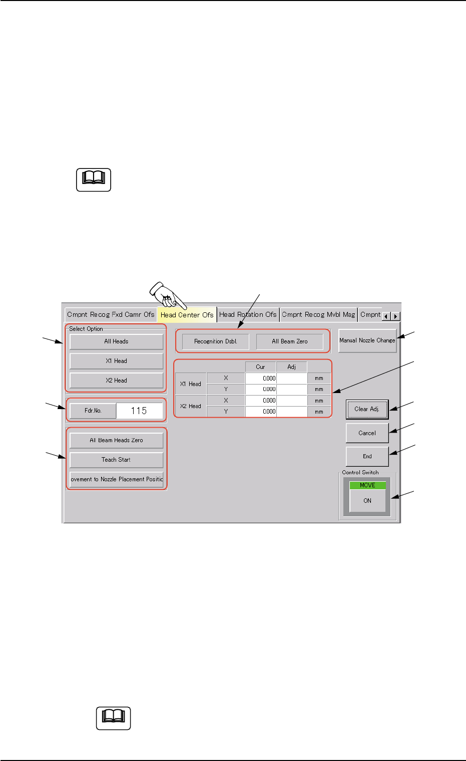
Fig. 2F114 "Head Center Ofs" Tab Sheet
• Sheet Composition
*1 "Select Option" Group Box
The following buttons are provided in this group box.
[All Heads] Button
When this button is pressed, the machine performs the teaching
operations on both heads.
Before performing the teaching operation, zero all beams.
Note
0206-002 6-166
5.9 "Head Center Ofs" Tab
Note
*1
*2
*10
*7
*6
*8
*9
*3
*5
*4

AHB01ESPP
[X1 Head] and [X2 Head] Buttons
When pressed, the button performs the teaching operation on
the corresponding head (X1 or X2).
Before performing the teaching operation, zero all beams.
*2 [Fdr. No.] Button
When this button is pressed, the "Fdr. No." edit window opens. En-
ter the feeder No. to which the head must be moved, using the ten-
key pad.
*3 "Selection of Teaching Operation" Group Box
The following buttons are provided in this group box.
[All Beam Heads Zero] Button
When this button is pressed, all X/Y beams are zeroed.
[Teach Start] Button
When this button is pressed, a teaching operation is performed
on the selected nozzle.
[Movement to Nozzle Placement Position] Button
When this button is pressed, the head moves to the specified
feeder No. (Fdr. No.) position.
*4 Set Status
When the "P.E.C. Dsbl." or the "Comp. Recognition Dsbl." check
box in the "Test Run" window is turned on (checked), the background
color of "Recognition Dsbl." turns light red. (No background color in
normal cases).
No recognition processing is made even if a teaching op-
eration is performed when each check box is turned on
(checked) in the "Test Run" window. Therefore, various
teaching operations will get incorrect results.
When "All Beam (Incl. NC Axis) Heads Zero" is completed, the back-
ground color of "All Beam Zero" turns green. (Otherwise, the back-
ground has no color.)
(a) When each device is not zeroed and the teaching op-
erations are performed, note that the offset values may
not be taught correctly.
(b) Before performing a teaching operation, be sure to zero
all beams.
Note
Note
0308-003 6-167
Note
5.9 "Head Center Ofs" Tab