2OM-1075-002.pdf - 第177页
AHB01ESPP (8) Check the temporarily registered data in the placement step. Press the [Place Pos] button (*1). (9) Use the vertical scroll bar in the step data area until the step to be checked appears. After that, select…

AHB01ESPP
(4) When the placement coordinates are regarded as a teaching point,
select the [1-Pt] or the [2-Pt] button in the "Teach Point" group box
(*12).
Component Outline Staying inside Recognition Window
Select the [1-Pt] button (Center of Component) in the "Teach Point"
group box.
Part of Component Outline Staying outside Recognition Win-
dow
Select the [2-Pt] button (Diagonal Corners of Component) in the
"Teach Point" group box.
In the case of "2-Point Teaching", the second point is automatically
selected after the first point is taught completely.
(5) Check the selection in the "Teach Point" group box and press the
[TEACH] button (*6). In 2 seconds, press the [ENABLE] button on
the operation panel. The teaching operation starts.
(6) Manipulate the pointing device such that the component outline in
the recognition window is aligned with the P.C.B. pattern that was
captured in the recognition memory.
Pointing Device Operation
Joystick : Movement of P.C.B. Pattern
Right-Clicking : Image Expansion
Left-Clicking : Image Reduction
Simultaneous Clicking
(Right- and Left-Clicking at Same Time)
: Alignment Completed
When the alignment is completed, new P.C.B. origin offsets are dis-
played in the "X (mm)" and "Y (mm)" text boxes of "Teach Result"
(*2).
(7) To temporarily register the new P.C.B. origin offsets, press the [Temp
Entry] button (*3).
The new P.C.B. origin offsets are written in a temporary file.
"Temp Entry" appears in place of "Current Value" (*2).
(a) When the new P.C.B. origin offsets are registered tempo-
rarily, the data for operations and the contents in the tem-
porary file (one of the files used for the current pattern pro-
gram) are re-written but the contents of the original file are
not.
(b) While the offsets are being registered temporarily, the can-
cel operation is available to cancel the temporary registra-
tion of the data.
To cancel the registration, press the [Cancel] button (*8).
0308-002 5-25-16
5.3 "PCB Origin Offset Teach" Tab
Note
AHB01ESPP
(8) Check the temporarily registered data in the placement step.
Press the [Place Pos] button (*1).
(9) Use the vertical scroll bar in the step data area until the step to be
checked appears. After that, select the step.
When the [Desig Step] button (*11) is pressed, the desired
step can be keyed in directly.
(10) Press the [Move to Teach Pt] button (*5) and the [ON] button (*10
entitled "MOVE"). In 2 seconds, press the [ENABLE] button on the
operation panel. The head moves to the position of the selected
step.
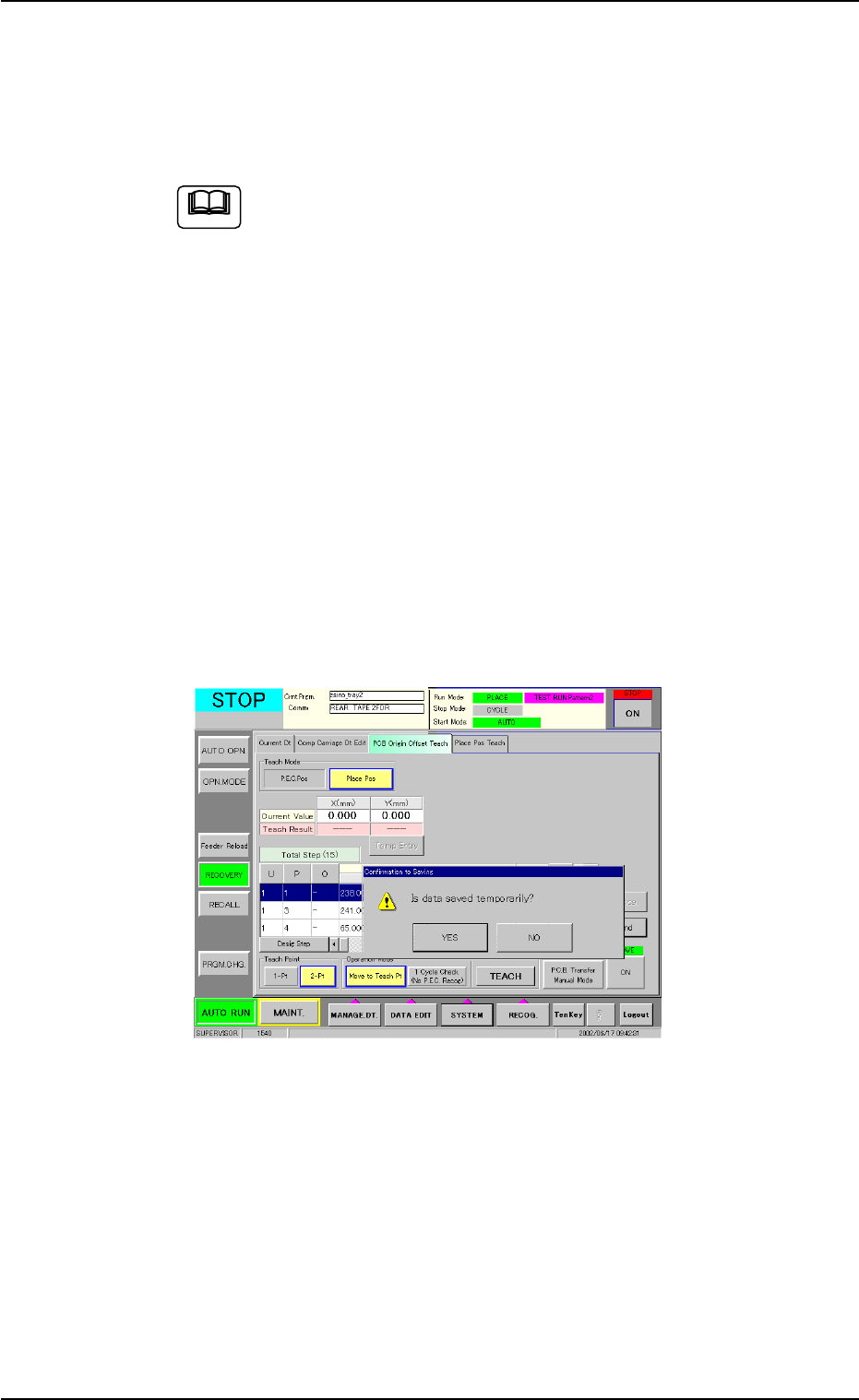
(11) To formally (not temporarily) register the new P.C.B. origin offsets,
press the [End] button (*9).
The "Confirmation to Saving" dialog box appears.
To replace the current pattern program data with the new one
(Save)
When the [YES] button is selected in the "Confirmation to Saving"
dialog box, the P.C.B. origin offsets are replaced with the tempo-
rarily saved ones.
Fig. 2E23-5 "Confirmation to Saving" Dialog Box
To keep the current pattern program data unchanged (Save
As)
When the [NO] button is selected in the "Confirmation to Saving"
dialog box, the "Input File Name" dialog box opens.
Enter a new file name and press the [Set] button.
The temporarily saved P.C.B. origin offsets are saved in a new file
having the newly entered name.
To discard the taught data (Cancellation of All Taught Data)
Press the [NO] button in the "Confirmation to Saving" dialog box.
0308-002 5-25-17
5.3 "PCB Origin Offset Teach" Tab
Note

AHB01ESPP
5.4 "Place Pos Teach" Tab
5.4.1 Scope
By capturing the image of P.C.B. patterns in the recognition window with
the P.E.C. recognition camera, it can be checked if wrong parameters
are specified individually as placement coordinates in the pattern pro-
gram.
When a mistake is found, this function can be used to correct the pat-
tern program data, using the manual alignment function (matching op-
eration of displayed component outlines and P.C.B. patterns with the
pointing device).
••
••
• Objective Data for Teaching
Placement Coordinates P1 to Pn Steps (X, Y) in Placement Data
(P-data)
Coordinates (X, Y) of Pattern Origin O1 to On in Placement Data
(O-data)
5.4.2 Cautionary Items on Teaching
••
••
• Before performing a teaching operation on the placement coordinates,
be sure to check if normal P.C.B. origin offsets are set or not in the
"PCB Origin Offset Teach" tab sheet.
If not, perform a teaching operation on the P.C.B. origin offsets be-
forehand.
••
••
• When the P.E.C. recognition is designated in the pattern program
data, all P.E.C. recognition processing must be completed before the
placement coordinates verification in the placement coordinates
teaching.
When the P.E.C. recognition is designated and a teaching operation
is started with the machine in the "STOP" mode, the machine ex-
ecutes the P.E.C. recognition function first.
••
••
• When the unit P.C.B. B.B.R. function (option) is designated in the
pattern program, the movement to the bad mark position and the
detection will not be made in the placement coordinates verification
of the placement coordinates teaching. The objects for teaching are
all unit P.C.B.’s.
5.4 "Place Pos Teach" Tab
0308-002 5-25-18