2OM-1075-002.pdf - 第185页
AHB01ESPP (8) Manipulate the pointing device such that the component outline in the recognition window is aligned with the P .C.B. pattern that was captured in the recognition memory . Pointing Device Operation Joystick …
AHB01ESPP
(4) Check how the component outline and the land pattern or the com-
ponent is captured in the recognition window and select the [1-Pt] or
the [2-Pt] button in the "Teach Point" group box (*2).
Component Outline Staying inside Recognition Window
Select the [1-Pt] button (Center of Component) in the "Teach Point"
group box.
Part of Component Outline Staying outside Recognition Win-
dow
Select the [2-Pt] button (Diagonal Corners of Component) in the
"Teach Point" group box.
In the case of "2-Point Teaching", the second point is automatically
selected after the first point is taught completely.
(5) Confirm that the cursor is located at the objective step for teaching.
(6) Confirm that the proper button is selected in the "Teach Point" group
box and press the [ENABLE] button on the operation panel in two
seconds after the [TEACH] button (*8).
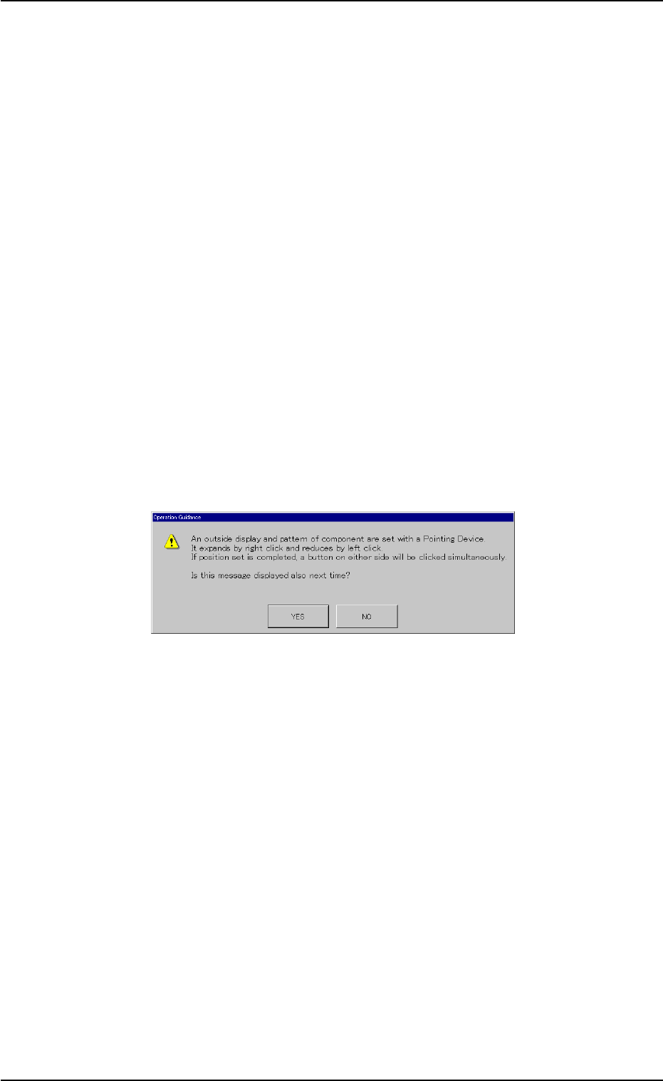
The "Operation Guidance" dialog box opens.
Fig. 2E23-8 "Operation Guidance" Dialog Box
(7) Press the [YES] button in the "Operation Guidance" dialog box.
0308-002 5-25-24
5.4 "Place Pos Teach" Tab
AHB01ESPP
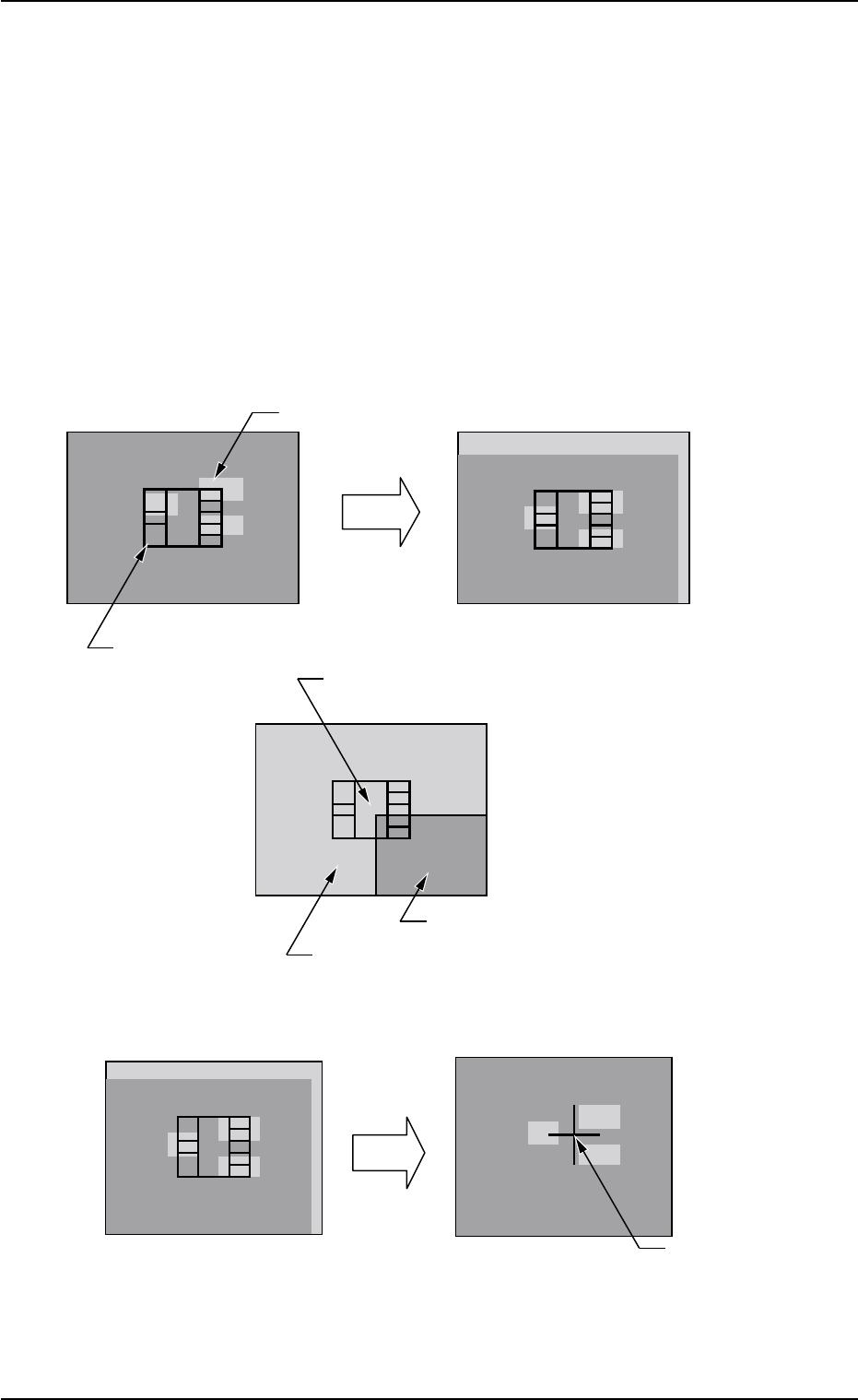
(8) Manipulate the pointing device such that the component outline in
the recognition window is aligned with the P.C.B. pattern that was
captured in the recognition memory.
Pointing Device Operation
Joystick : Movement of P.C.B. Pattern
Right-Clicking : Image Expansion
Left-Clicking : Image Reduction
Simultaneous Clicking
(Right- and Left-Clicking at Same Time)
: Alignment Completed
Case: 1-Point Teaching
Fig. 2E23-9 Teaching Operation for "1-Point Teaching"
0308-002 5-25-25
C=P1
X=OOO Y=OOO
P.C.B. Pattern
Movement
Manipulate the pointing device to move the P.C.B. pattern.
Component Outline
The P.C.B. pattern can be moved up to the point
where the four corners of the window are aligned
with the center of the monitor.
Image inside View
Image outside View
After the alignment is completed, press the right and left buttons of the pointing device to
determine the position.
Determination
of Position
Press the right and left buttons of the pointing device at the same time.
The determined
position is indicated
by a blue cross.
5.4 "Place Pos Teach" Tab
AHB01ESPP
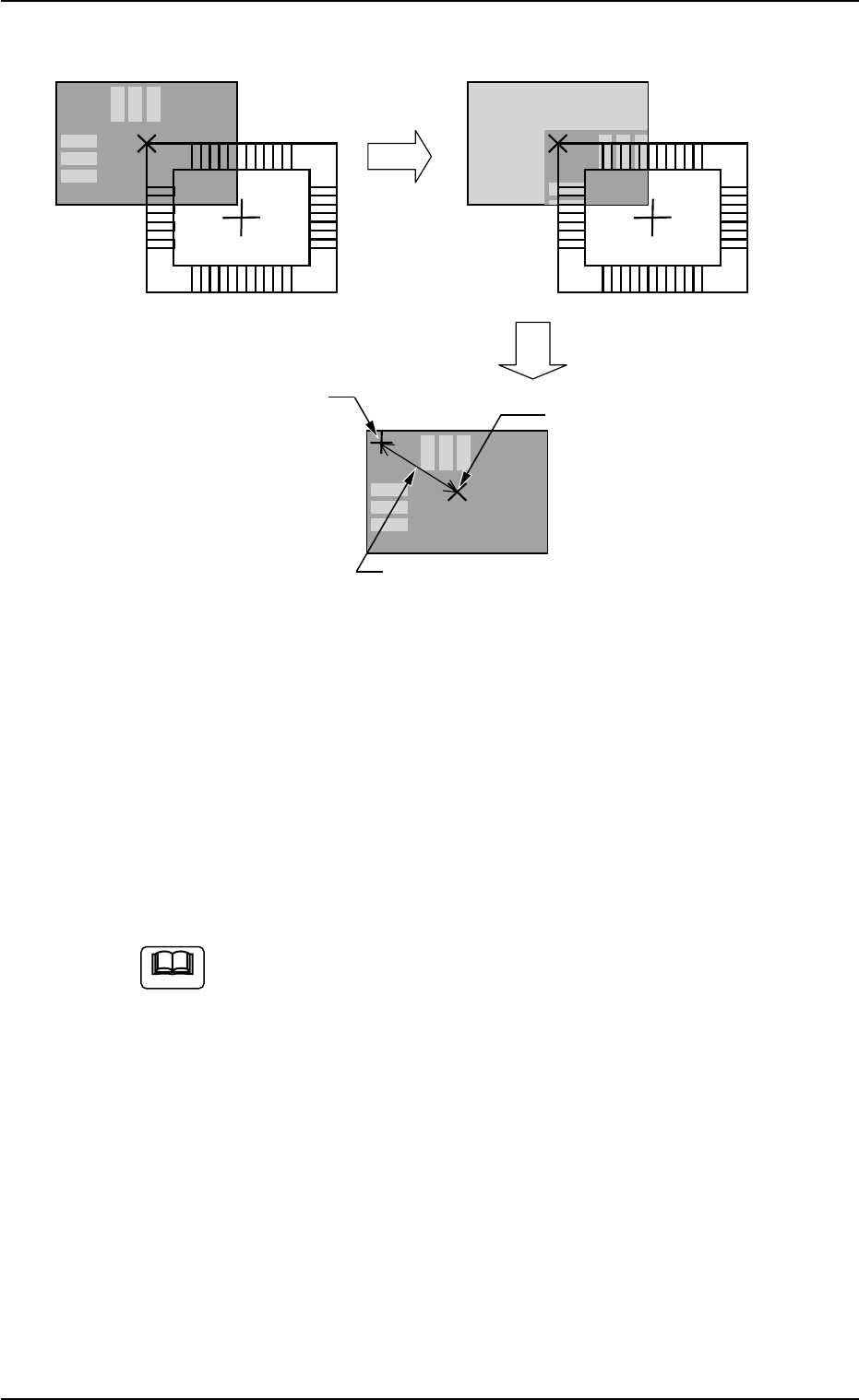
Case: Diagonal 2-Point Teaching
Fig. 2E23-10 Teaching Operation for "2-Point Teaching"
(9) When the teaching is completed, new placement coordinates are
displayed in the "X (mm)" and "Y (mm)" text boxes of "Teach Result"
(*3).
(10) To temporarily register the new placement coordinates, press the
[Temp Entry] button (*4).
The new placement coordinates are written in a temporary file.
"Temp Entry" appears in place of "Current Value" (*3).
(a) When the new placement coordinates are registered tem-
porarily, the data for operations and the contents in the
temporary file (one of the files used for the current pattern
program) are re-written but the contents of the original file
are not.
(b) While the steps are being registered temporarily, the can-
cel operation is available to cancel the temporary registra-
tion of the data.
To cancel the registration, select the objective step and
press the [Cancel] button (*10).
(c) As for the step being registered temporarily, the background
color in the step data area turns blue.
(d) The temporarily registered data is reflected immediately
upon the automatic (continuous) and step operations.
0308-002 5-25-26
Teaching
Determination of Position
The determined position is
indicated by a blue cross.
Center of Window
Not displayed in actual cases.
The distance is determined based
on the center of the window.
C=P1 X=OOO Y=OOO
5.4 "Place Pos Teach" Tab
Note