2OM-1075-002.pdf - 第156页
AHB01ESPP 3. 6 "Camera Bypass" T ab The corresponding tab sheet enables the operator to operate the ma- chine without using the specified camera(s). • • • • • Sheet Layout When the "Camera Bypass" tab…
AHB01ESPP
3.5 "Head/Noz. Bypass" Tab
The corresponding tab sheet enables the operator to operate the ma-
chine without using the specified head(s) or nozzle(s).
••
••
• Sheet Layout
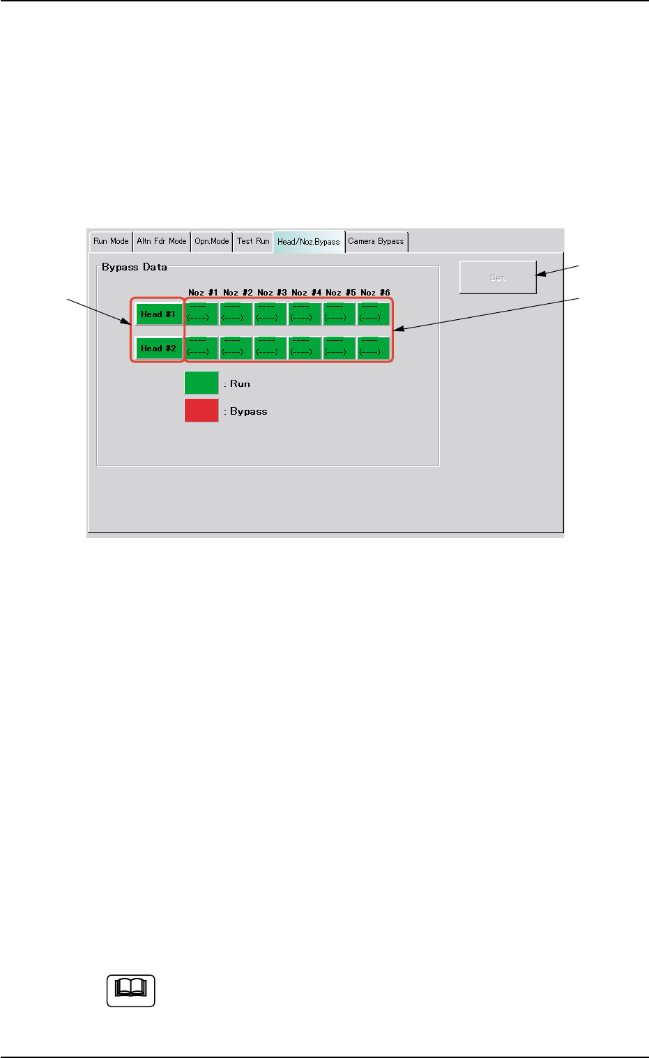
When the "Head/Noz. Bypass" tab is pressed in the "OPN. MODE"
window (submenu), the following tab sheet appears inside the win-
dow.
Fig. 2E15 "Head/Noz. Bypass" Tab Sheet
••
••
• Sheet Composition
*1 [Head #1] and [Head #2] Buttons
Select the head(s) to be bypassed.
Every time a button is pressed, it turns green or red.
Green : Working (Available)
Red : Bypassed (Unavailable)
*2 [Noz #1] through [Noz #6] Buttons on Head #1 and [Noz #1]
through [Noz #6] Buttons on Head #2
Select the nozzle(s) to be bypassed.
Every time a button is pressed, it turns green or red.
Green : Working (Available)
Red : Bypassed (Unavailable)
*3 [Set] Button
After specifying the nozzles to be bypassed, press the [Set] button
to save this data.
When the machine is set in the "RUN" or the "WAITE" mode,
the setting operation cannot be performed.
The operation is possible only when the machine is set in the
"STOP" mode.
3.5 "Head/Noz. Bypass" Tab
*1
*2
*3
0206-001 5-24-1
Note
AHB01ESPP
3.6 "Camera Bypass" Tab
The corresponding tab sheet enables the operator to operate the ma-
chine without using the specified camera(s).
••
••
• Sheet Layout
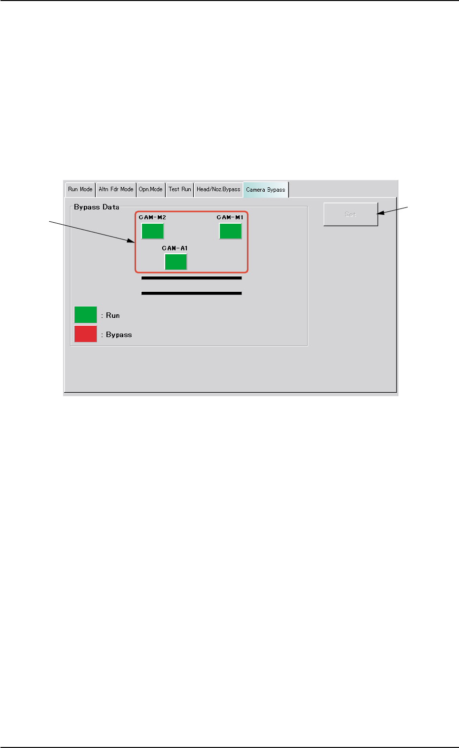
When the "Camera Bypass" tab is pressed in the "OPN. MODE"
window (submenu), the following tab sheet appears inside the win-
dow.
Fig. 2E15-1 "Camera Bypass" Tab Sheet
••
••
• Sheet Composition
*1 [CAM-M1], [CAM-M2], and [CAM-A1] Buttons
Select the camera(s) to be bypassed.
[CAM-M1] : Movable Camera 1
[CAM-M2] : Movable Camera 2
[CAM-A1] : Fixed Camera A1
Every time each button is pressed, it turns green or red.
Green : Working (Available)
Red : Bypassed (Unavailable)
*2 [Set] Button
After specifying the camera(s) to be bypassed, press the [Set] but-
ton to save this data.
3.6 "Camera Bypass" Tab
*2
*1
0308-002 5-24-2
AHB01ESPP
4. "Feeder Reload" Window (Submenu)
0308-001 5-24-3
4. "Feeder Reload" Window (Submenu)
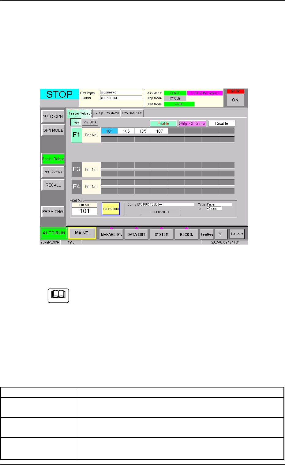
This window can be used to cancel the component shortage mode.
• Window Layout
When the [Feeder Reload] button on the submenu bar of the "AUTO
RUN" window is pressed, the following window (submenu) appears.
Fig. 2E15-2 "Feeder Reload" Window (Submenu)
(Provided with Multi-Layer Tray Feeder 2)
The window may look different, depending on which options are
selected.
• Window Composition
*1 Tabs and Tab Sheets
The "Feeder Reload" window (submenu) is provided with the fol-
lowing tab sheets.
Table 2E2-2
Tabs Description
Feeder Reload The corresponding tab sheet enables the operator to cancel the
component shortage mode for the production model.
Pickup Tray Matrix This is an optional function. Refer to the instruction manual of the
multi-layer tray feeders for details.
Tray Comp. Dt This is an optional function. Refer to the instruction manual of the
multi-layer tray feeders for details.
Note