2OM-1075-002.pdf - 第203页
AHB01ESPP 0308-004 5-41 7. "PRGM. CHG." Window (Submenu) • • • • • Window Layout When the [PRGM. CHG.] button on the submenu bar of the "AUTO RUN" window is pressed, the following window (submenu) ope…

AHB01ESPP
Note
(a) Insert a formatted floppy disk (1.44MB DOS-formatted disk)
in the floppy disk drive of the service panel.
(b) Up to 3 image planes (resolution: 100%) can be saved on
one piece of floppy disk. (Excluding any divided recogni-
tion error)
(c) Do not press the eject button of the disk drive when the
access lamp is ON. Otherwise, the data stored on the in-
serted floppy disk may be corrupted.
(d) When the access lamp of the FDD extinguishes, it indi-
cates that the data is saved completely. Press the eject
button and take out the floppy disk from the disk drive.
(e) When the error image analysis must be performed on the
manufacture’s side, set the following before the image is
saved.
Set "1 (100% Resoln)" in the "# of images" text box of
"Recog error image save" in the "Auto Operation Setup"
tab sheet. (Operation Sequence: [SYSTEM] Button on Main
Menu Æ "SYS DATA" Menu Æ "Machine System Data"
Window Æ "Auto Operation" Tab Æ "Auto Operation Setup"
Tab)
Refer to "2.2 "Auto Operation" Tab" in "Section 5 System
Setting" of "Vol. 3: Programming and Machine Data" for
details.
6.6 "Recog. Image" Tab
0308-003 5-40
AHB01ESPP
0308-004 5-41
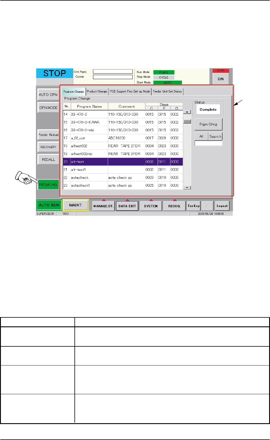
7. "PRGM. CHG." Window (Submenu)
••
••
• Window Layout
When the [PRGM. CHG.] button on the submenu bar of the "AUTO RUN"
window is pressed, the following window (submenu) opens.
Fig. 2E35 "PRGM. CHG." Window (Submenu)
••
••
• Window Composition
*1 Tabs
The "PRGM. CHG." window (submenu) is provided with the follow-
ing 4 tabs. When a tab is pressed, the corresponding tab sheet ap-
pears inside the window.
Table 2E8
Tabs Description
Program Change The corresponding tab sheet enables the operator to select a pat-
tern program as a current one (model) for automatic operation.
Product Change The corresponding tab sheet enables the operator to perform over-
all setup operations or manual setup operations on each device.
PCB Support Pins The corresponding tab sheet enables the operator to set the envi-
Set-up Mode ronmental condition required to determine the position of the P.C.B.
support pins.
Feeder Unit Set Status The corresponding tab sheet enables the operator to confirm the
required feeders and check if the correct feeders are actually
installed on the feeder bases.
7. "PRGM. CHG." Window (Submenu)
*1
AHB01ESPP
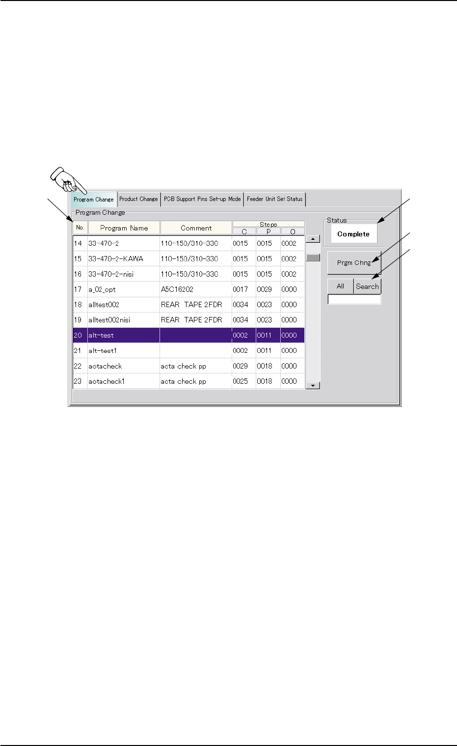
7.1 "Program Change" Tab
The corresponding tab sheet enables the operator to select a pattern
program as a current one (model) for automatic operation.
••
••
• Sheet Layout
When the "Program Change" tab is pressed in the "PRGM. CHG." win-
dow (submenu), the following tab sheet appears inside the window.
Fig. 2E36 "Program Change" Tab Sheet
••
••
• Sheet Composition
*1 List of Model Names
Listed are the registered model names (pattern program names).
*2 Status
Displayed is the result of implemented program change operation.
*3 [Prgm Chng] Button
When this button is pressed, the current model (pattern program) is
changed to another one.
7.1 "Program Change" Tab
0308-004 5-42