00195941-03-UM SiplaceCA-EN.pdf - 第110页
2 Operational Safety User Manual SIPLACE CA 2.11 Energy State after Switching Off at the Main Switch Edition 08/2011 EN 110 The following table specifies th e voltages of mo dules when the automatic placement system is s…
User Manual SIPLACE CA 2 Operational Safety
Edition 08/2011 EN 2.11 Energy State after Switching Off at the Main Switch
109
2
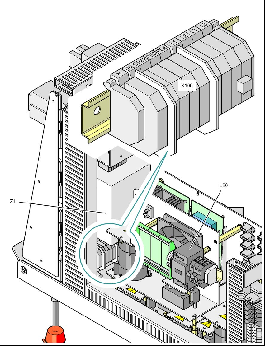
Fig. 2.11 - 5 Power supply unit, back view
X100 Cable connection terminal for the power supply cable
L20 Discharge reactor with fuses F21, F22 and F23
Z1 Line filter
2 Operational Safety User Manual SIPLACE CA
2.11 Energy State after Switching Off at the Main Switch Edition 08/2011 EN
110
The following table specifies the voltages of modules when the automatic placement system is
switched off at the main switch, but still connected to the main supply.
2
Module Voltage
Terminal panel X100
Line filter Z1
Terminals L1, L2, L3
3 x 208 VAC
3 x 230 VAC
3 x 380 VAC
3 x 400 VAC
3 x 415 VAC
Service socket X102
120 VAC
130 VAC
220 VAC
230 VAC
240 VAC
Automatic circuit breaker F1
120 VAC
130 VAC
220 VAC
230 VAC
240 VAC
Main switch Q1
Terminals L1, L2, L3
3 x 208 VAC
3 x 230 VAC
3 x 380 VAC
3 x 400 VAC
3 x 415 VAC
Main switch Q1
Terminals T1, T2, T3
0 VAC
Power supply unit
(see item 5 of fig. 2.9 - 2
)
Test socket X11
GND X12
Test socket X13_1
Test socket X13_4
GND X13_7
< 10 VDC
< 10 VDC
< 10 VDC
Computer unit (see fig. 2.11 - 3
)
Test socket + 12 VDC
Test socket - 12 VDC
Test socket + 15 VDC
Test socket -15 VDC
Test socket + 5 VDC
Test socket + 52 VDC
Test socket + 3.3 VDC
GND
0 VDC
0 VDC
0 VDC
0 VDC
0 VDC
0 VDC
0 VDC
User Manual SIPLACE CA 2 Operational Safety
Edition 08/2011 EN 2.12 Lock Out and Tag Out Procedure
111
2.11.1.2 Placement System Switched off at the Main Power Switch and Disconnected ...
The automatic placement system is unpowered, apart from slight residual voltages in the power
supply unit.
The SWS must be separately disconnected from the mains power supply!
2.11.1.3 Compressed Air Conditions in the Machine after Switching off at the Main
Power Switch
When switching off the main switch (item 1 of fig. 2.11 - 1) or if the main power supply to the ma-
chine fails, the electrically controlled main valve Y1 of the compressed air unit (item 1 of fig. 2.10
- 1). The pressure will drop to 0 MPa (0 bar) within 5 seconds.
2.11.2 Main switch at the SWS
Each SWS has its own main switch for the voltage supply.
2.12 Lock Out and Tag Out Procedure
CAUTION 2
The following instructions also apply to the SWS modules.
2.12.1 Purpose and Scope
Before performing any preventive maintenance work or service work, a procedure of locking and
tagging must be followed. The procedure, when followed correctly eliminates the possibility of an
employee being injured.
NOTE
This process contains the minimum requirements for locking the machine or attaching warning la-
bels to the machine for maintenance or service work. Any additional safeguards needed to com-
plete work safely can be specified by facilities supervision, the safety officer, the safety committee
and the health department. 2