00195941-03-UM SiplaceCA-EN.pdf - 第200页
3 Technical Data User Manual SIPLACE CA 3.8 Placement Heads Edition 08/2011 EN 200 3 Fig. 3.8 - 10 6 segment Collect&Plac e CA head - function groups part 2 3 (1) Intermediate distributo r b oard, beneath the cover (…
User Manual SIPLACE CA 3 Technical Data
Edition 08/2011 EN 3.8 Placement Heads
199
3.8.5 6 Segment Collect&Place CA Head
3
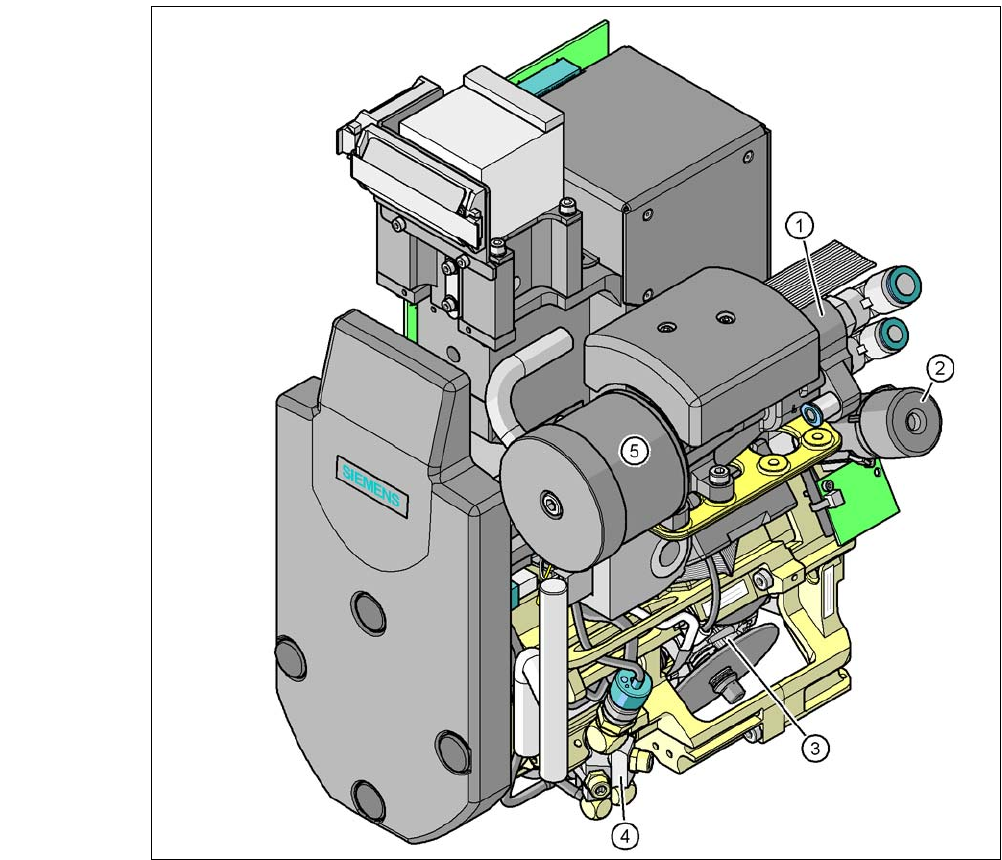
Fig. 3.8 - 9 6 segment Collect&Place CA head - function groups part 1
(1) Vacuum generator
(2) Turning station, DP axis
(3) Star with 6 sleeves, star axis
(4) Air kiss valve
(5) Silencer
3 Technical Data User Manual SIPLACE CA
3.8 Placement Heads Edition 08/2011 EN
200
3
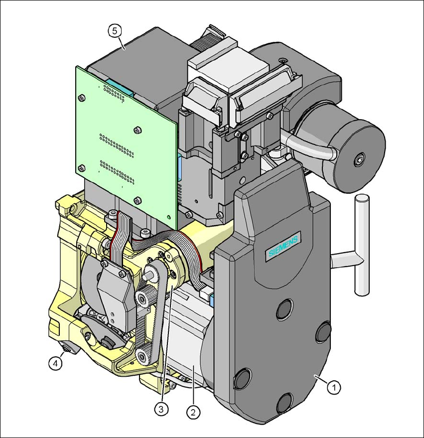
Fig. 3.8 - 10 6 segment Collect&Place CA head - function groups part 2
3
(1) Intermediate distributor board, beneath the cover
(2) Star drive - DR motor
(3) Z axis motor
(4) Valve positioning drive
(5) C&P component camera, type 29, 27 x 27, digital
User Manual SIPLACE CA 3 Technical Data
Edition 08/2011 EN 3.8 Placement Heads
201
3.8.5.1 Description
The 6 segment Collect&Place CA head also functions according to the Collect&Place principle.
With the high-resolution digital component camera, the 6 segment Collect&Place CA head accu-
rately and rapidly places components with an edge length of up to 27 mm. It is therefore ideal for
use with products containing a large proportion of ICs. A considerable increase in output can be
achieved even in the main application range from PLCC 44 to QFP 208.
3.8.5.2 Control and Self-Learning Functions
The control and self-learning functions described on page 196 for the 12 segment Collect&Place
CA head also apply to the 6 segment Collect&Place CA head.
3.8.5.3 Functional Description
3
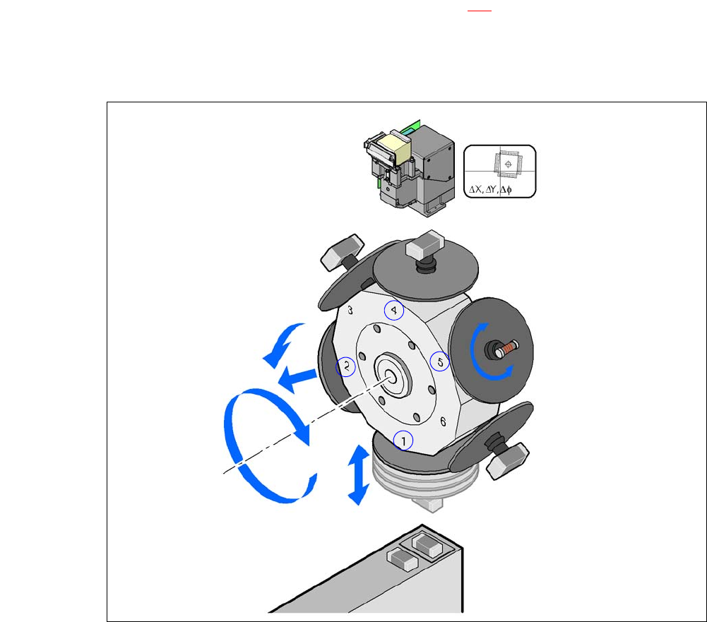
Fig. 3.8 - 11 Functional Description
The 6 segment Collect&Place CA head consists of three axes, the DR or star axis, the Z-axis
and the DP axis.
Component camera
DP axis
Rotate component
into placement position
Remove or insert sleeve
Z axis
Pick up component
or place it
Star axis
Star rotation
Reject component