00195941-03-UM SiplaceCA-EN.pdf - 第403页
User Manual SIPLACE CA 6 Component and Die Handling Edition 08/2011 EN 6.2 Component Trolley, SIPLACE X-Series 403 6.2.1 Structure of the Compone nt T rolley SIPLACE X Series The component trolley essentially consist s o…
6 Component and Die Handling User Manual SIPLACE CA
6.2 Component Trolley, SIPLACE X-Series Edition 08/2011 EN
402
The component trolleys are independent modules, which can be set up with feeder modules at an
external set up location. This means that the production process only has to be interrupted briefly
in order to change the component trolley.
6
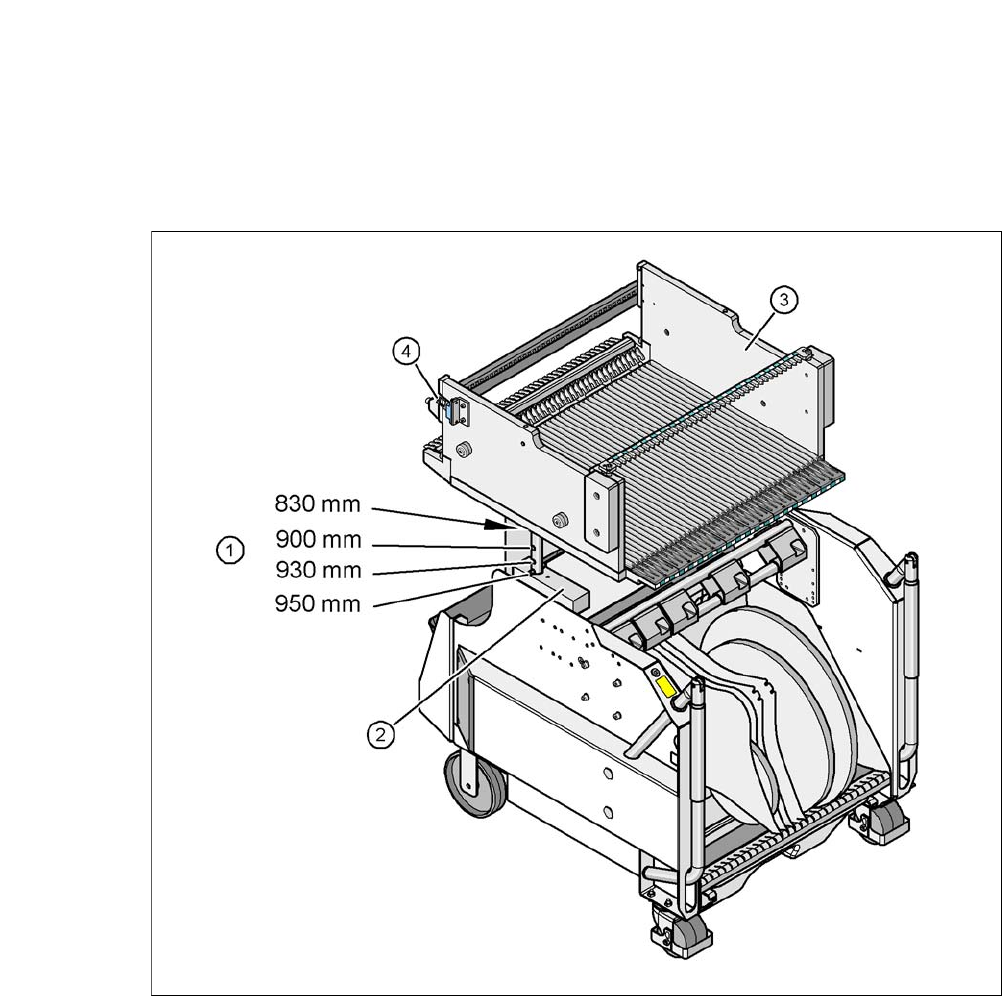
Fig. 6.2 - 2 Component trolley, SIPLACE X-series with a PCB conveyor height of 950 mm
6
(1) Holes for the PCB conveyor heights 900, 930 and 950 mm in the guide columns. For the
830 mm conveyor height, the component table lies on the block (2).
(2) Supporting block
(3) Component table
(4) Reed switch for switching the safety switch in the component trolley docking unit
User Manual SIPLACE CA 6 Component and Die Handling
Edition 08/2011 EN 6.2 Component Trolley, SIPLACE X-Series
403
6.2.1 Structure of the Component Trolley SIPLACE X Series
The component trolley essentially consists of the chassis, the component table for holding the
feeder modules, the tape reel container and the waste tape bin.
6
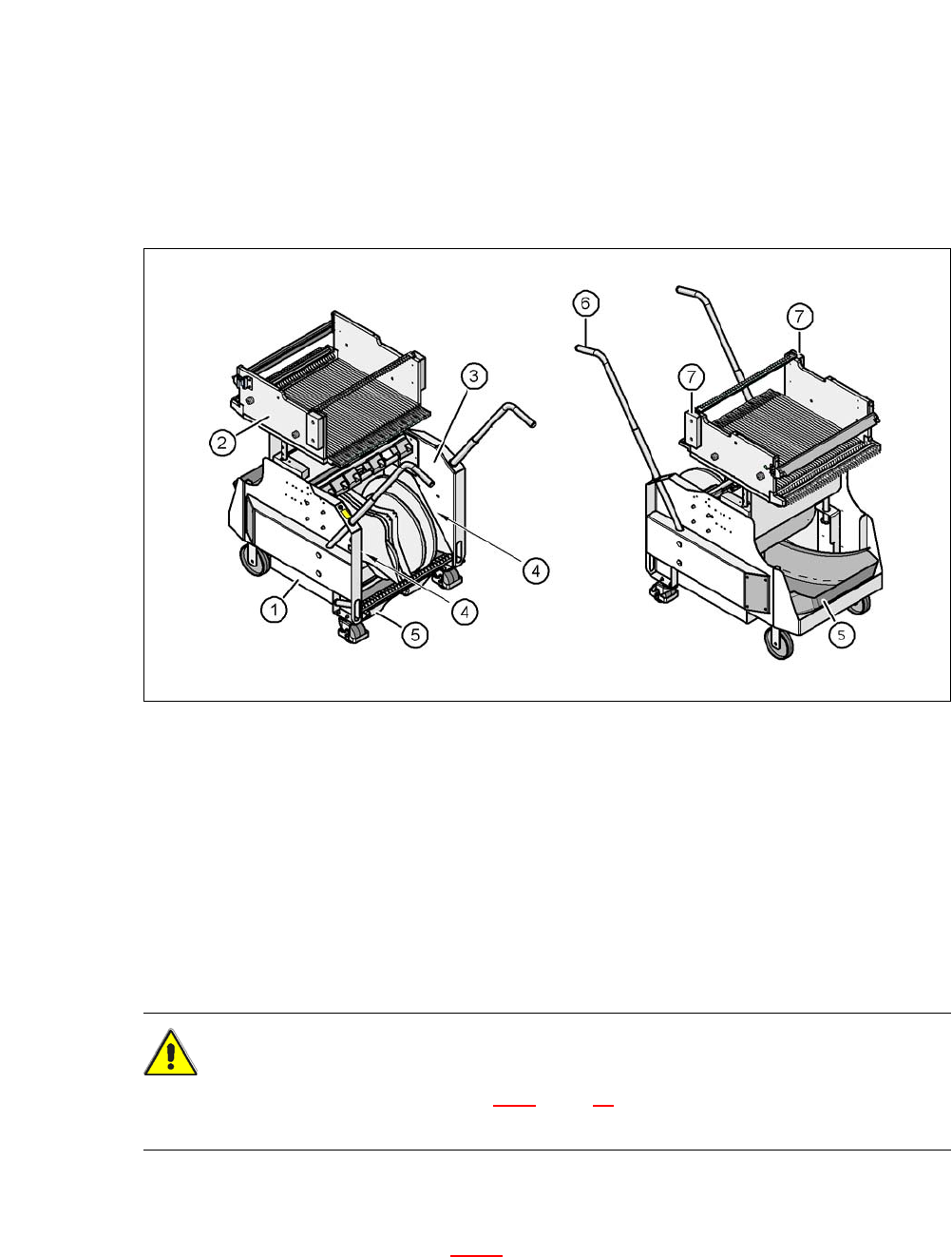
Fig. 6.2 - 3 Component trolley, SIPLACE X-series, front and back view
(1) Chassis
(2) Component table
(3) Tape container
(4) Gap for setup lists
(5) Waste bin for unused tape
(6) Handle
(7) Hand guard
CAUTION 6
Observe the safety instructions in section 2.6.8
, page 75, when you pull the tape reject bin out of
the component trolley.
Assemblies 6
The tape reel container (item 3 in fig. 6.2 - 3) can accommodate tape reels up to a size of 17" (432
mm), in its standard version.
6 Component and Die Handling User Manual SIPLACE CA
6.2 Component Trolley, SIPLACE X-Series Edition 08/2011 EN
404
Between the tape container and the component trolley, there are two 5 mm wide gaps (item 4 in
fig. 6.2 - 3
) - on the left and right - for accommodating setup lists.
The pullout waste tape container (item 5 in fig. 6.2 - 3
). The cut waste tape travel down a channel
into the waste tape bin, which must be emptied as it fills up.
The handles (item 6 in fig. 6.2 - 3
) can be folded out upwards or downwards.
NOTE ON OPERATIONAL SAFETY 6
All component trolleys or matrix tray changers must be docked on the machine in order to oper-
ate it. Fit free locations with dummy feeders, as described in section 2.8.5, page 97.
6.2.2 Technical Data for the SIPLACE X Series Component Trolley
6
6
Length x width 727 mm x 592 mm
to 752 mm x 592 mm with waste bin
Height of the component table 819.5 mm for 830 mm PCB conveyor height
889.5 mm for 900 mm PCB conveyor height
919.5 mm for 930 mm PCB conveyor height
939.5 mm for 950 mm PCB conveyor height
PCB transport height 830 mm ± 15 mm (standard)
900 mm ± 15 mm (option)
930 mm ± 15 mm (option)
950 mm ± 15 mm (SMEMA option)
Height of the folded up handles 969 mm
Number of locations 40 (8 mm X tape feeder module)
Weight
without feeder modules
with feeder modules on all locations
80.4 kg
139.6 kg
Reel diameter
Standard
Maximum
Up to 432 mm (17")
483 mm (19")