00195941-03-UM SiplaceCA-EN.pdf - 第357页
User Manual SIPLACE CA 5 Tasks on the Machine Edition 08/2011 EN 5.5 Configuring Fee ders 357 5 Fig. 5.5 - 6 Operator panel of the feeder module (1) FOR WARD bu tton for moving the componen t tape for ward (2) BACK butto…
5 Tasks on the Machine User Manual SIPLACE CA
5.5 Configuring Feeders Edition 08/2011 EN
356
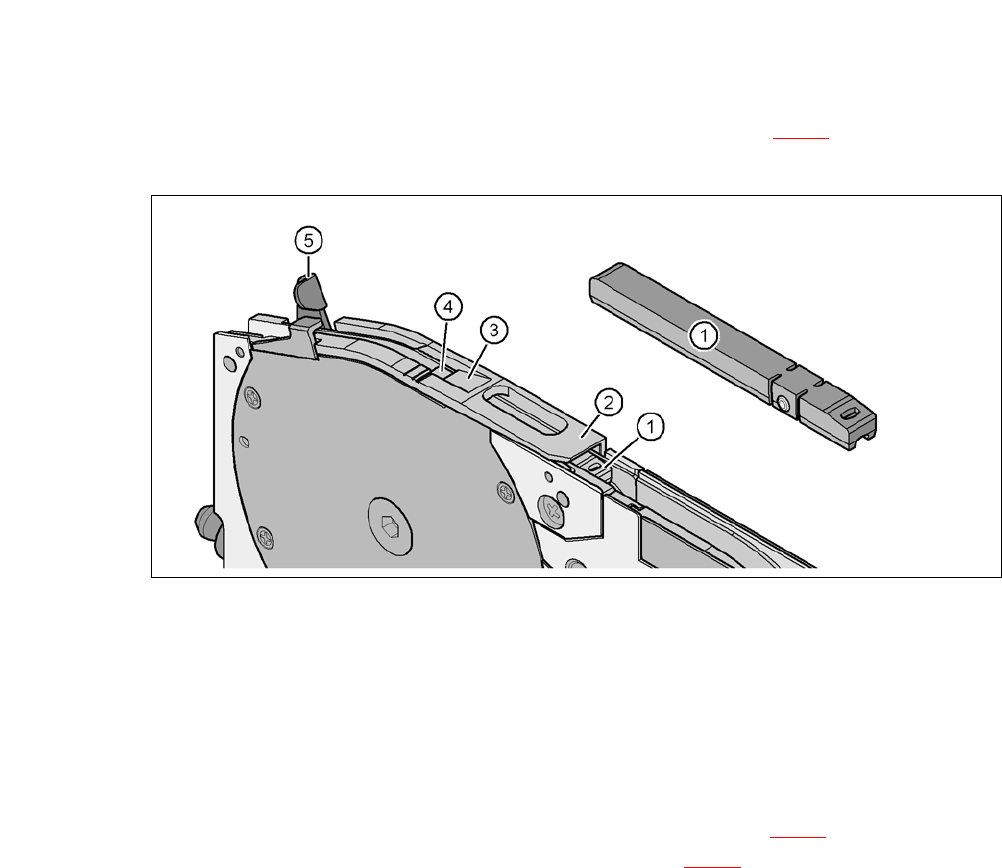
Guide the start of the tape under the pickup window (item 2 in fig. 5.5 - 5) and on, until the
tape touches the sprocket wheel.
5
Fig. 5.5 - 5 Pickup window on the tape feeder module
(1) Tape support, removable
(2) Pickup window
(3) Pull-off edge for the cover foil
(4) pickup area for the components
(5) Lever for raising and latching the pickup window
Press the FORWARDS button on the operator panel (item 1 in fig. 5.5 - 6) until the fold in the
cover foil is in the component pickup area (item 4 in fig. 5.5 - 5
).
User Manual SIPLACE CA 5 Tasks on the Machine
Edition 08/2011 EN 5.5 Configuring Feeders
357
5
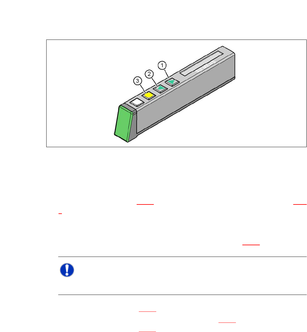
Fig. 5.5 - 6 Operator panel of the feeder module
(1) FORWARD button for moving the component tape forward
(2) BACK button for moving the component tape back
(3) FOIL button for tensioning the cover foil
Press the lever (item 5 in fig. 5.5 - 5) forwards, to raise the pickup window (item 2 in fig. 5.5 -
5) into the first engage position.
Pull the cover foil at the side of the pickup window forward and out underneath the pickup
window.
Move the cover foil back, until it is on the pull-off edge (item 3 in fig. 5.5 - 5).
NOTE 5
Do not lower the pickup window until the cover foil is lying against the pull-off edge.
Swing the lever (item 5 in fig. 5.5 - 5) back, to lower the pickup window.
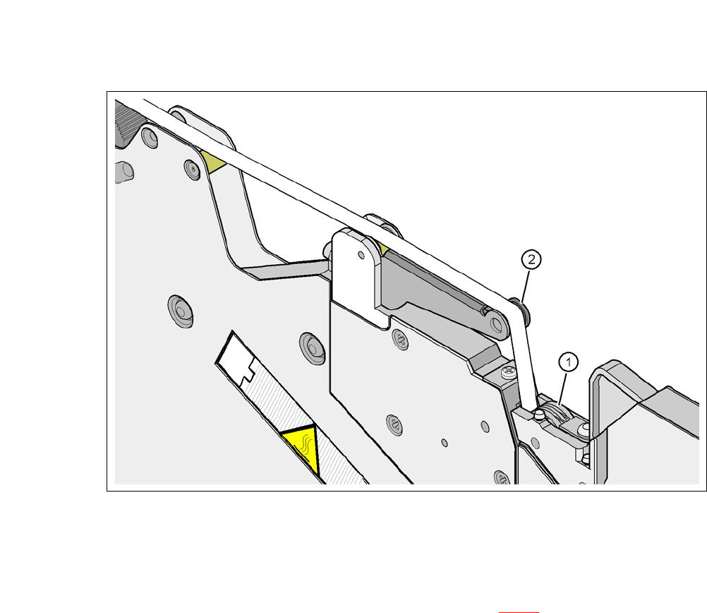
Guide the cover foil over the cover foil rocker (item 2 in fig. 5.5 - 7) until it reaches the foil
packing wheels (item 1 in fig. 5.5 - 7
).
5 Tasks on the Machine User Manual SIPLACE CA
5.5 Configuring Feeders Edition 08/2011 EN
358
5
Fig. 5.5 - 7 Guiding the cover foil to the foil packing wheels
(1) Cover foil packing wheels
(2) Cover foil
5
Press the FOIL button on the operator panel (item 3 in fig. 5.5 - 6) until the cover foil is ten-
sioned. The cover foil rocker points down and stops the drive motor.
Cut the component tape flush with the front end of the feeder module.