00195941-03-UM SiplaceCA-EN.pdf - 第225页
User Manual SIPLACE CA 3 Technical Data Edition 08/2011 EN 3.13 Vision Cameras 225 3.13.1.2 IC and FC Cameras on the CA3 Machines 3 Fig. 3.13 - 2 IC and FC Cameras on the CA3 Machines C&P C&P20CA, C&P12CA or …
3 Technical Data User Manual SIPLACE CA
3.13 Vision Cameras Edition 08/2011 EN
224
3.13.1 Assembly Positions for the Stationary Cameras - IC Camera and FC Camera
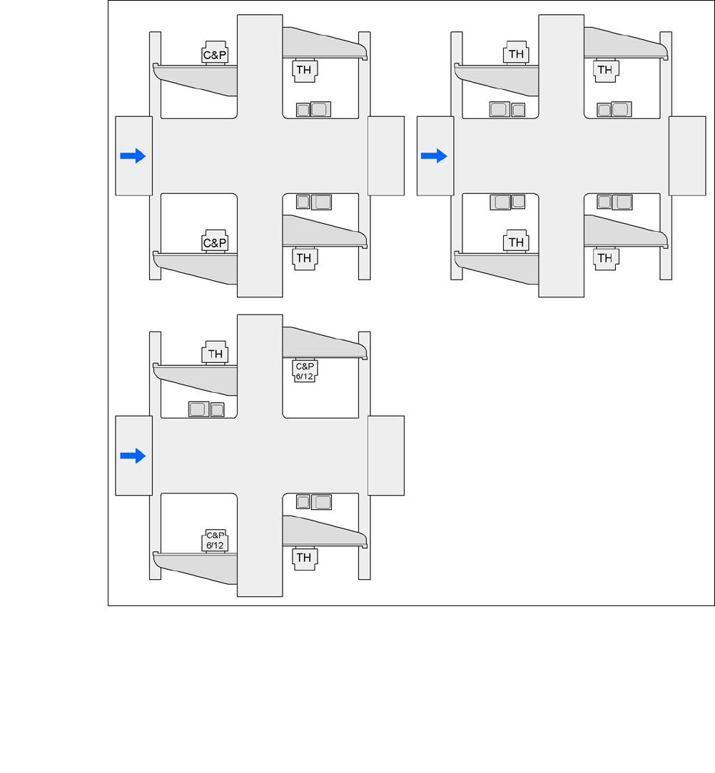
3.13.1.1 IC and FC Cameras on the CA4 Machines
3
Fig. 3.13 - 1 IC and FC Cameras on the CA4 Machines
C&P C&P20CA, C&P12CA or C&P6CA
C&P6/12 6 segment Collect&Place CA head or 12 segment Collect&Place CA head
TH TwinHead
25 FC camera, type 25
33 IC camera, type 33
P1, P2, P3, P4 gantry 1, gantry 2, gantry 3, gantry 4
33 and 25
25 and 33
25 or 33 33 or 25
33 or 25
25 or 33
25 or 33
G3
G3
G4
G4
G1
G2
G2
G1
G4
G3
G2
G1
25 or 33
User Manual SIPLACE CA 3 Technical Data
Edition 08/2011 EN 3.13 Vision Cameras
225
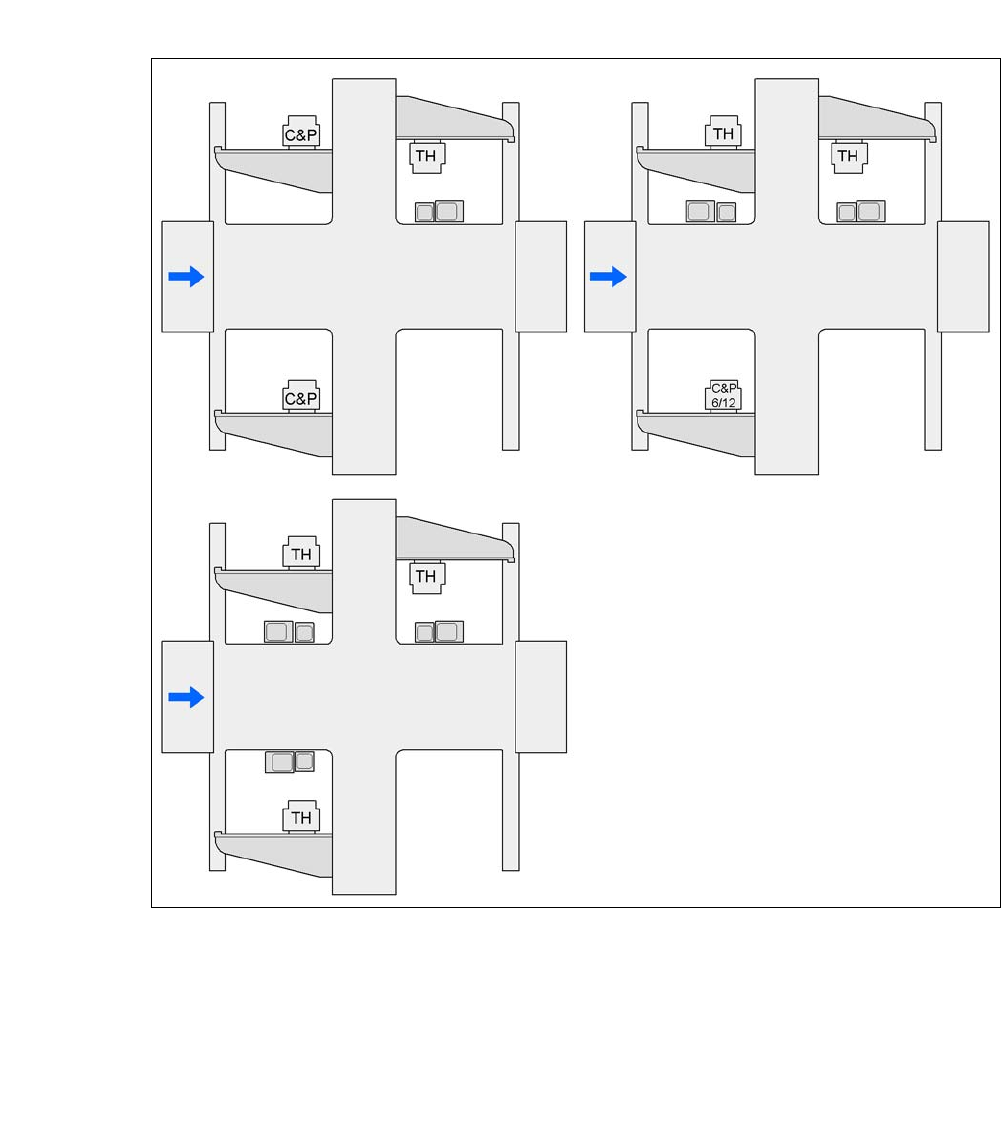
3.13.1.2 IC and FC Cameras on the CA3 Machines
3
Fig. 3.13 - 2 IC and FC Cameras on the CA3 Machines
C&P C&P20CA, C&P12CA or C&P6CA
C&P6/12 6 segment Collect&Place CA head or 12 segment Collect&Place CA head
TH TwinHead
25 FC camera, type 25
33 IC camera, type 33
P1, P2, P3, P4 gantry 1, gantry 3, gantry 4, gantry
33 or 25
25 and 33
25 and 33 33 and 25 25 and 33
33 or 25
G3 G3
G4
G4
G1
G1
G4
G3
G1
3 Technical Data User Manual SIPLACE CA
3.13 Vision Cameras Edition 08/2011 EN
226
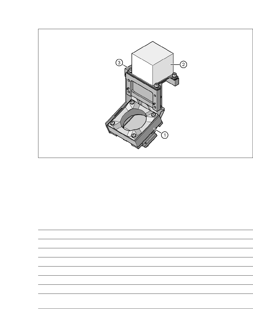
3.13.2 Component Camera C&P, Type 23, 6 x 6, Digital
3.13.2.1 Structure
3
Fig. 3.13 - 3 C&P component camera, type 23, 6 x 6, digital
3
(1) Component camera lens and illumination
(2) Camera amplifier
(3) Illumination control
3.13.2.2 Technical Data
3
Component dimensions 0,18 mm x 0,18 mm to 6 mm x 6 mm
Range of components 01005 to 6 mm x 6 mm
Min. lead pitch 0.25 mm
Min. lead width 0.1 mm
Min. ball pitch 0.13 mm
Min. ball diameter 0.08 mm
Field of vision 8,4 mm x 8,4 mm
Illumination method Front-illumination (5 levels, programable as re-
quired)