00195941-03-UM SiplaceCA-EN.pdf - 第326页
4 Setting Up and Commissioning User Manual SIPLACE CA 4.6 Installing the SWS Edition 08/2011 EN 326 4 Fig. 4.6 - 4 Picture showing the position of screws for the SWS at the SIPLACE location Y ou can now remove the fork…
User Manual SIPLACE CA 4 Setting Up and Commissioning
Edition 08/2011 EN 4.6 Installing the SWS
325
4.6.3.4 Final Adjustment of the SWS
Use the fork-lift truck or hand lift to push the SWS carefully into the placement machine, as
far as the stop on the bumper.
Carefully lower the SWS with the fork-lift truck or hand lift, until it lies evenly on the contact
bars of the placement machine.
CAUTION 4
Make sure that you do not lower the hand lift too far, before fastening the screws, as the SWS
will then tip over towards the magazine lift. 4
A second person should check the stability of the SWS during lowering. 4
The following screws are needed to install the SWS:
–3x M8
–2x M6
– 4x M6 for the angle bracket (2 at the location, 2 at the wafer table)
– 1x fitting screw
Note: 4
During final installation, observe the following order of screws.
Fasten the rear clamping claw (6) loosely, with one M8 screw.
Insert the remaining screws and tighten loosely.
NOTE 4
The correct position of the SWS is ensured with the help of the fitting screw and the contact
rods in the placement machine. 4
Fasten the M6 screws (item 4 and 5) in succession, with a torque of 10 Nm.
Fasten the M8 screws (item 1, 2 and 6) in succession, with a torque of 18 Nm.
Tighten the fitting screw in item 3 with a torque of 13-14 Nm.
Tighten the angle bracket for fixing the wafer table with the M6 screws (items 7 and 8).
Fix the angle bracket with the M6 screws to the wafer table.
4 Setting Up and Commissioning User Manual SIPLACE CA
4.6 Installing the SWS Edition 08/2011 EN
326
4
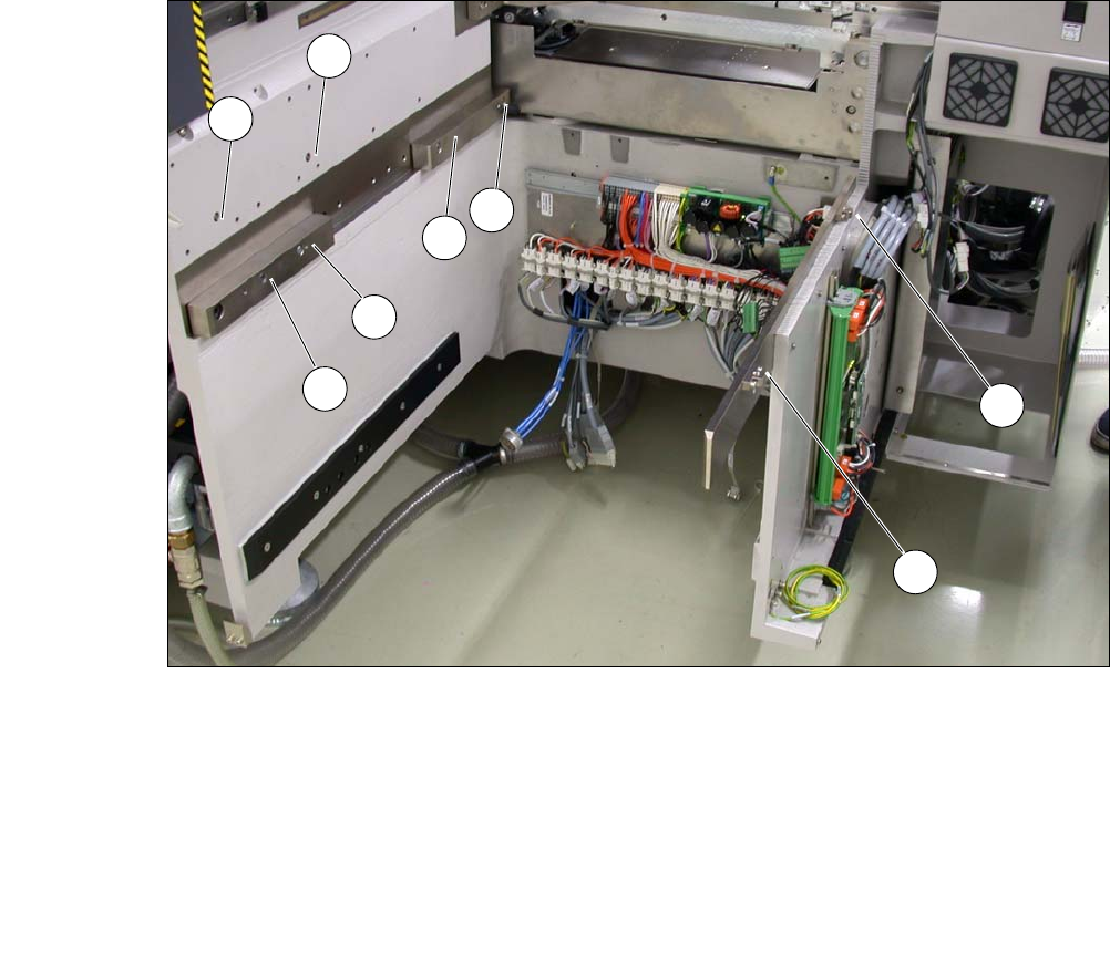
Fig. 4.6 - 4 Picture showing the position of screws for the SWS at the SIPLACE location
You can now remove the fork-lift truck or hand-lift.
(1) M8 (2) M8
(3)Fitting screw (4)M6
(5) M6 (6) M8 for clamping claw
(7) M6 for angle bracket (8) M6 for angle bracket
2
3
5
4
1
7
8
6

User Manual SIPLACE CA 4 Setting Up and Commissioning
Edition 08/2011 EN 4.6 Installing the SWS
327
4.6.4 Removing the Transportation Locks
– Remove all transport locks:
– Flip rotary axis
– Wafer table (X/Y axis)
– Wafer changer feed axis (if present)
4.6.5 Removing the Corrosion Protection from the Guide Rails
Check whether the SWS has been treated with corrosion protection agent. This must be removed
before setting up the SWS.
CAUTION 4
– You should therefore remove the corrosion protection from all the axes and bearings when
you traverse the machine axes for the first time during commissioning.
– Grease all the axes and bearings with the grease described in the maintenance instructions.
If the corrosion protection agent is mixed with the bearing grease on the axes this can greatly re-
duce the service life of the bearings and guide rails.
CAUTION 4
Do not allow any alcohol to enter the guide carriages when you clean the guide rails and scale
rods. Alcohol will damage the bearing grease in the guide carriages.
4.6.6 Power Supply
After performing final adjustment, connect the SWS to the power supply.