00195941-03-UM SiplaceCA-EN.pdf - 第313页
User Manual SIPLACE CA 4 Setting Up and Commissioning Edition 08/2011 EN 4.5 Setting Up the Placement Machine 313 4.5.16 Integrating the Placem ent Machine into the Line Observe the warnings in section 4.5.2 , page 267…
4 Setting Up and Commissioning User Manual SIPLACE CA
4.5 Setting Up the Placement Machine Edition 08/2011 EN
312
4
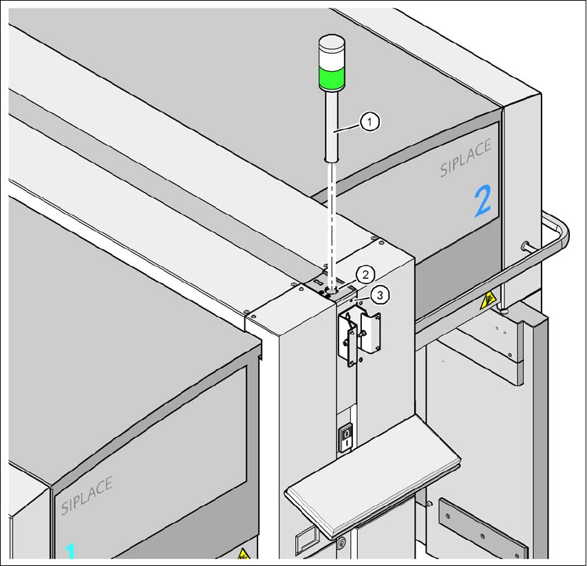
Fig. 4.5 - 24 Fitting the main indicator lamp
(1) Main indicator lamp
(2) Hole for the main indicator lamp
(3) Hole for the locking screw
4.5.15 Fixing the Monitor
Fix the monitor into place and connect the cables.
Check the cable connections
User Manual SIPLACE CA 4 Setting Up and Commissioning
Edition 08/2011 EN 4.5 Setting Up the Placement Machine
313
4.5.16 Integrating the Placement Machine into the Line
Observe the warnings in section 4.5.2, page 267.
For information about tools and equipment, refer to section 4.5.3, page 268.
4.5.16.1 Position Fork Lift Truck
4
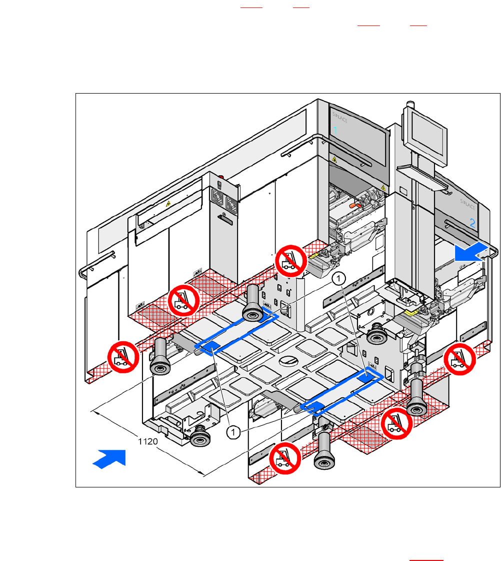
Fig. 4.5 - 25 Contact surfaces - Forks across the direction of PCB transport
(1) Contact surfaces for the forks of the fork-lift
Position the fork-lift truck at right angles to the PCB conveyor and open the forks until the con-
tact surfaces of the placement machine lie evenly on the forks (see fig. 4.5 - 25
).

4 Setting Up and Commissioning User Manual SIPLACE CA
4.5 Setting Up the Placement Machine Edition 08/2011 EN
314
WARNING 4
Before lifting the placement machine, observe the following points to avoid causing irreversible
damage to the machine:
– The distance between the forks must be between 800 and 900 mm. The attachment points
for the fork-lift truck can be seen in fig. 4.5 - 25
. The outer distance between the machine feet
is 1120 mm. Make sure you do not increase the distance between the forks so that the place-
ment machine is lifted under the sides of the machine frame, as this would distort the machine
frame.
When lifting the placement machine, make sure that the forks are loaded evenly. A firm sup-
port surface between the fork and the machine prevents the machine from tipping over when
lifted. This will also prevent a one-sided load on the machine feet, which would deform the
fixing of the machine feet. We recommend that a second person monitors the lifting of the ma-
chine and ensures that the placement machine does not tip over to one side when lifted by
the fork-lift truck.
4.5.16.2 Points that MUST be Noted when Transporting the Placement Machine
WARNING 4
When you are transporting the machine, make sure that all the feet are clear of the floor. If the
machine feet should drag along the floor during transportation or hit an obstacle, this could dam-
age the fixtures for the machine feet in the placement machine!